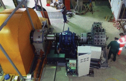
Piper Test and Measurement (PT&M) manufactures engine test systems that include their own dynamometers. PT&M was asked to supply a braking system for the flywheel generator that consisted of a hydraulic dynamometer and a water-cooled disc brake. With this braking system, the flywheel can come to a standstill in less than 10 min. The motor-generator was positioned on a concrete block connected to the floor of the building where it is housed.
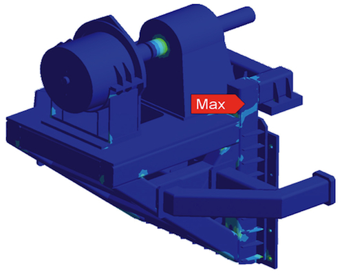
This ANSYS solid model shows Von Mises stress contours on the flywheel structure.
PT&M contacted engineering and consulting bureau IDAC to perform FEA to evaluate the design of a support structure for the braking system. The analysis work was divided into three phases.
Phase one: A topological optimization was performed to determine a preliminary design of the support frame. This work was done using ANSYS Mechanical Shape Optimizer. The software approximated the initial structure as a large volume which was then “eaten away” at locations with low stresses, leaving a pixelated representation of the optimized support structure. An envelope of the initial volume was defined to locate the soleplates for the support structure and to define the position of the side arms. The loading consisted of a static load (weight of the components and platform) and a dynamic load (reaction torque applied by the dynamometer and disc brake).
Phase two: Engineers performed a design optimization in ANSYS Mechanical APDL. A parametric model of beam and shell elements was created. The sizes and thicknesses of the beams and shells respectively were defined as design variables and the mass of the structure as the objective function. The natural frequency was defined as a state variable and the mass of the structure as the objective function to ensure that the natural frequencies of the steel support structure avoided the critical resonant frequencies of the concrete foundation block.
The design optimization refined the support structure, beams, and plates. These data were forwarded to Whittaker Engineering, the support structure manufacturer that made some manufacturing modifications to the design. In return, the company provided IDAC with an Autodesk Inventor model of the structure for further analysis.

Technicians install the flywheel generator. It consists of a dynamometer and a water-cooled disc braking system.
Phase three: Engineers used the Inventor model in ANSYS Mechanical to mesh the solid model of beams and shells with solid elements and then re-analyze them to verify the final design of the support structure.
The use of ANSYS Mechanical to optimize the shape optimization within of the support structure for the 11-ton brake assembly delivered a design that made use of minimum weight and space while giving a reliable design and cost saving. The results from the analyses also showed that maximum performance was attained while avoiding the modes of resonance of the concrete foundation block.
ANSYS, Inc.
www.ansys.com
Piper Test and Measurement
www.piper-ltd.co.uk
IDAC
www.idac.co.uk
::Design World::
Filed Under: Software • 3D CAD, Software • FEA, Software • simulation, ENGINEERING SOFTWARE, MECHANICAL POWER TRANSMISSION, TEST & MEASUREMENT


Tell Us What You Think!