This article, second in a series, shows how new virtual prototyping tools help you master increasing machine complexity, fix mistakes and optimize design of mechatronics systems.

Analyze the system performance and provide valuable input for motor tuning.
Machinery design today requires us to demonstrate skills like multidisciplinary knowledge, excellent communication capabilities, and inquisitiveness. If you find yourself contemplating modern machines and commenting to colleagues about how things seemed simpler back in the old days, you are not alone.
For many years faster, better and cheaper was the credo for machine design engineers. Energy efficiency and smaller footprint recently made this list. The solution for all those constraints is often the adoption of new technologies like high-end control systems, sophisticated algorithms and a multitude of electronic components, turning a machine into a mechatronic system.
Consequently design complexity has increased with the size of design teams, and the different design groups are forced to work closer together. In a mechatronic system every decision made has a ripple effect throughout the design project. If the mechanical team decides to change the type of steel being used, and therefore the weight of a mechanical component, it influences motor sizing. Switching from a stepper motor to a servomotor significantly increases the complexity of the control algorithm and the requirements concerning the system performance of the embedded system processing the algorithm.
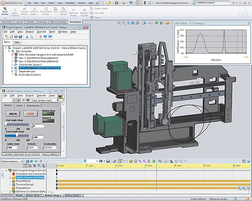
The concept of “virtual machine prototyping” connects motion control software and simulation tools to create a virtual model of an electromechanical machine in operation. Virtual prototyping helps you reduce risk and tackle design challenges for mechatronic systems by locating system-level problems, finding inter-dependencies and evaluating performance trade-offs.
Challenge 1: Selecting mechanical components
Your design will typically start with creating a 3D CAD model and selecting the correct mechanical components. One of the most common tasks within industrial machines involves moving an object from one position to another using an electric motor. A common way to change the rotary motion of a standard electric motor to useful linear motion is by connecting the motor to a stage and using a lead screw mechanism to move the payload. Some of the key items to consider when selecting a stage include the resolution, the travel distance, the payload and the transmission gear ratio.
While some of those parameters are mainly defined by the mechanical design, specifying the transmission gear ratio (Nr) requires collaboration with the control team. From a mechanical standpoint, Nr specifies the linear travel distance of the stage per rotary revolution of the motor. Looking at the control side of the design, Nr has a significant influence on the payload inertia reflected to the motor, which has a huge impact on the control algorithms. As a rule of thumb, the gear ratio, Nr, should be selected such that the ratio between the reflected inertia and the motor shaft inertia is less than 10:1 for velocity control, 5:1 for moderate positioning, and 2:1 for quick positioning. Otherwise stability and tuning problems may occur. In addition the transmission ratio also determines the motor speed requirements in relation to the load speed.

Design and validate your motion profiles using interference detection features.
Linear stages move in a straight line and are often stacked on each other to achieve travel in multiple directions. A three-axis system with a X, Y and Z component is a common setup used to position an object anywhere in a 3D space. Linear stages are used to position an object in space, rotary stages are used to orient objects in space and adjust the roll pitch and yaw of an object. Many applications, such as very high-precision alignment, require both position and orientation. Specifying stacked systems which combine linear and rotary components is even more complex because inertias, forces and torques that arise during operation are difficult to calculate.
The simulation capabilities of state-of-the-art 3D CAD tools can help in gathering the required information. Combined with the real-world trajectories from motion control software you can simulate real-world behavior and get the information without performing PhD-level math calculations.

Challenge 2: Motion profile design and validation
Often machine builders have switched from single-purpose machines to creating flexible multipurpose machines, where mechanical and pneumatic components are substituted with motor based solutions. One example for such a replacement is mechanical shafts, which perform camming. In modern machines they are often replaced by a combination of multiple drives and motors, requiring the control software to provide the camming function. While this results in machines that are easier to maintain, have a smaller footprint and have significant efficiency advantages, designing the motion profiles for these systems gets more complex with every additional motor and moving component.

Visualize compliance issues like motor ringing due to resonance.
Developing the motion profiles requires specialized software tools. Usually control engineers don’t want to create the algorithms, which control the flow of energy within the coils of the motor. Instead they want to design their system based on functions that perform standard move types like straight line, arc, or contoured moves. In addition they require advanced features to synchronize multiple motors through gearing and camming functions.
In traditional design flows, control engineers usually couldn’t start implementing algorithms before a first physical prototype was built. Now, the integration of the LabVIEW NI SoftMotion and SolidWorks allows control engineers to design and validate their motion profiles as soon as a 3D CAD model is available, allowing engineers and scientists to create a virtual prototype of their cartesian motion system. By applying the motion profile developed with the high-level function blocks to a simulation-ready 3D CAD model, they can evaluate and validate the operation of moving parts and determine whether the motion profile performs as expected.
Challenge 3: Motor selection/force torque
Motor sizing seems pretty simple — just pick the best motor to match the speed, inertia and torque requirements of your application. However, the DOE estimates that about 80% of all motors used in the US are oversized. Although modest oversizing compensates for rising friction over the life of the machine, going too far decreases performance because of higher inertia, lower motor operating efficiency and higher energy costs. This is even more important when the motor is part of the payload, as in many multi-axis motion control systems. Approximately 96% of the lifetime cost of a motor comes from the energy it consumes, rather than the cost of buying the motor itself.

Define motor specifications based on the results of your motion simulation.
Several web-based motor-sizing tools have been designed to help sort through the thousands of choices, and some include motor data from multiple vendors. However, these tools are only as good as the inputs you provide. You can augment the tools by using features built into your CAD package to make more accurate estimates of your speed, inertia, and torque requirements.
Using realistic, multi-axis motion profiles to drive your simulation can provide more accurate torque and velocity requirements, which depend on the acceleration characteristics of your motion profiles and the mass, friction and gear ratio properties of the transmission. When evaluating simulation results, compare RMS values for torque and velocity with the rated performance curve for the motor, and compare peak values with the maximum velocity and intermittent torque limits.
The proper motor must be paired with the mechanical system to provide the performance required. There are four main motor technologies available:
Challenge 4: Mechanical compliance
Mechanical compliance issues that lead to unintended vibrations are one of the most common causes of problems in the machine industry. Physical phenomena like flexibility and backlash can wreak havoc on the closed-loop PID control system making it difficult or impossible to tune, or causing the system to literally hum during operation. Fixing the problems just in the controls software is impossible. Therefore dealing with compliance usually requires the redesign of mechanical components.
Linear compliance problems are caused by the flexibility of mechanical assemblies, such as the gripper arm in a pick-and-place machine. The length of the moment arm, the weight of the payload and the speed of the motion profiles all play a role. Because standard transmission components like lead screws tend to be quite stiff if you stay within the manufacturer’s specifications, linear compliance issues typically manifest themselves in the custom-designed mechanical assemblies you attach to the actuators. Most of the time, a mechanical team considers compliance issues when it designs the assemblies, but incorrect assumptions about operational forces and torques may lead to problems.
The most common control system workaround is to add extra dead time to the end of each move operation, to literally wait for the vibrations to settle. In some cases, running the motion profiles faster can actually reduce symptoms by shifting the excitation frequency of the motion trajectories above the natural frequency of the mechanical system. If the system is detuned by reducing the PID gains to avoid the problem, cycle time performance may suffer. Therefore the best way to fix the problem is typically a mechanical change.
You can avoid resonance by using different mechanisms. Among the first ones to consider are mechanical variations. By changing motor or load inertias or increasing transmission stiffness, you can move frequency resonance so that it does not appear in machine operation ranges. Again, virtual prototyping tools can test the design and root out problems while the machine is still just a virtual CAD model. You can apply real-world motion trajectories to the mechanical model and simulate the complete system to evaluate different design concepts before building an expensive physical prototype.
Challenge 5: DC motor system tuning
Once the previous elements are fixed a challenging time comes – making the machine work, balancing different aspects like machine performance and the stress placed onto the motors to increase the lifespan and reduce the number of required service trips. While it does not matter whether the motors used are low-cost steppers or high-end servos, tuning is one of the critical processes that will make the machine operate smoothly and efficiently while avoiding undesired behaviors like mechanical compliance.
Badly tuned motors can really decrease the machine performance and lifespan. When motors are not tuned properly, bad behavior will be exposed, such as motor overheating and damaging, poor quality on the final product, and mechanical jerks that stress the components beyond their original specification. It is not uncommon to tune the controller for a lower performance while increasing the specs for the motor so that it operates in a safer zone. Once this was a valid approach but tends to be less acceptable today since it increases machine weight and cost.
Discuss this on the Engineering Exchange:
National Instruments
ni.com
Dassault Systèmes SolidWorks Corp
solidworks.com
To see virtual prototyping demonstration videos and learn more, visit www.ni.com/virtualprototyping.
::Design World::
Filed Under: Software • 3D CAD, ENGINEERING SOFTWARE, Mechatronics


Great article! CAD modeling tools have certainly come a long way over the years and have helped engineers cut down on time and cost wasted in design iterations. I’m personally interested in how the virtual world interfaces the real world when metal gets cut and assemblies are built and tested. Of course, it’s awesome when your design is perfect and it all comes together without a hitch, but my experience is the perfect situation is the exception and not the rule. Would be very interested to see coverage of tools that help bridge the gap between virtual design and real world fabrication.