Ordinary vapor-compression cooling is inefficient and un-green. Future-generations of air conditioning may instead use electrocaloric techniques with almost no moving parts.
Leland Teschler • Executive Editor
Here’s some bad news about our warming world, courtesy of the International Energy Agency: The use of air conditioners and electric fans already accounts for about a fifth of the total electricity in buildings around the world – or 10% of all global electricity consumption. And most homes in hot countries have yet to purchase their first A/C. So over the next three decades, the use of A/C is likely to soar, becoming one of the top drivers of global electricity demand. The IEA figures that by 2050, around two-thirds of the world’s households could have A/C. China, India and Indonesia will together account for half the total.
Another fun fact about the year 2050 is that the evaporative cooling techniques used for A/C and refrigeration today probably can’t be improved enough to be practical thirty years from now. The IEA thinks energy demand for space cooling could consume as much electricity as all of China and India do today.
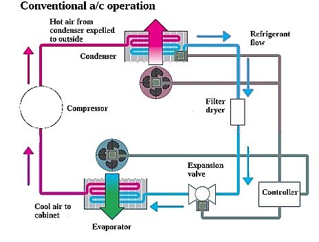 As a quick review, cooling in traditional A/C takes place via the vapor-compression cycle, which uses the phase change between gas and liquid of a refrigerant to transfer heat. All such systems have four components: a compressor, a condenser, a metering device or thermal expansion valve, and an evaporator. Circulating refrigerant enters the compressor as a saturated vapor and is compressed to a higher pressure, resulting in a hot superheated refrigerant vapor. The superheated vapor passes through the condenser where it cools and condenses completely, and the rejected heat is expelled. The condensed liquid refrigerant then passes through an expansion valve where it undergoes an abrupt reduction in pressure that causes a flash evaporation of a part of the liquid refrigerant, lowering the temperature of the liquid and vapor refrigerant mixture so it is colder than the temperature of the space to be refrigerated.
The cold mixture then passes through the coil or tubes in the evaporator. A fan circulates the warm air to be cooled across the evaporator coil or tubes. That warm air evaporates the liquid part of the cold refrigerant mixture. Meanwhile, the circulating air is cooled and thus lowers the temperature of the space to be cooled. Finally, the refrigerant vapor from the evaporator is again routed back into the compressor.
Conventional vapor-compression A/C equipment isn’t particularly green. Today it uses refrigerants comprised of hydrofluorocarbons which, though more environmentally friendly than previous generations of fluids, have a warming potential thousands of times higher than that of carbon dioxide. In addition, A/C equipment has a limited energy efficiency. In the U.S., the DoE dictates that residential units have an energy efficiency of at least 13 SEER (seasonal energy efficiency ratio). The SEER rating of a unit is the cooling output during a typical cooling-season divided by the total electric energy input during the same period. Thermodynamics efficiencies are usually calculated as a COP (coefficient of performance), the ratio of cooling provided to the energy required. A SEER of 13 is approximately equivalent to a COP of 3.2, which means that 3.2 units of heat are removed from indoors per unit of energy used to run the A/C.
The COP of an air conditioner, which follows a Carnot thermodynamic cycle, depends on the outside and inside temperatures. If the outdoor temperature is 95°F (35°C) and the indoor temperature is 80°F (27°C), the maximum theoretical Carnot cycle COP is 36. Unfortunately, it looks as though future COP improvements in vapor-compression A/C are likely to be just incremental at best. More efficient compressors and valves, better heat-transfer surfaces, and more exotic refrigerants are all on the drawing board. But all such advances are likely to be more costly and bring limited benefits.
Consequently, there is a great amount of interest in novel cooling methods that are potentially more energy efficient. In particular, solid-state methods are attractive because eliminate the inefficiencies that arise from friction, wear, and other losses. Perhaps the most well-known means of solid-state cooling takes the form of Peltier modules which work thanks to the thermoelectric effect. Here a voltage is applied across two special joined semiconductors to create an electric current. When the current flows through the junctions of the two conductors, heat is removed at one junction and deposited at the other, thus cooling the first junction.
A typical Peltier module consists of an array of alternating n- and p- type semiconductors having complementary Peltier coefficients. (Peltier coefficients basically denote the heat energy per electron per unit time carried to the junction.) The array of elements spans between two ceramic plates, electrically in series and thermally in parallel. Materials used are often bismuth telluride, antimony telluride, and bismuth selenide, selected for a combination of low thermal conductivity and high electrical conductivity.
Though Peltier type coolers have niche applications, they are unlikely to be practical for ordinary refrigeration or A/C. Thermoelectric junctions devised to date have a COP that is about 25% of that for vapor compression setups. That puts them at about 10–15% of the ideal Carnot cycle refrigeration efficiency compared with 40–60% for conventional A/C. Indications are that despite decades of intensive research, fundamental material and form-factor limitations may thwart attempts to realize Peltier energy efficiencies approaching that of traditional A/C, let alone produce something better.
Fortunately, there are other emerging technologies that may fare better when it comes to energy efficiency. Among them is electrocaloric (EC) cooling. Certain EC materials change temperature under an applied electric field. The underlying mechanism of the effect is complicated, but an applied voltage basically raises or lowers the entropy of the material.
In recent years, researchers have devised thin films of lead, titanium, oxygen and zirconium (PZT) that would cool down by 12°C under a 480 kV/cm field change. And there is progress in developing EC materials that exhibit “giant” EC effects. But it has proven to be tough getting the EC effect in components with thermal masses higher than that of thin films. That’s a necessary development for devising practical A/C systems employing EC cooling.
Fortunately, ceramic capacitors show promise as EC components. Recently, a group hailing from Xerox Parc and Murata Manufacturing in Japan described an EC cooler employing lead, scandium, tantalum (PST) multilayer ceramic capacitors (MLCCs) as the working elements. A 10.8 MV/m field changes the MLCC temperature by 2.5°C at room temperature. Moreover, the researchers say their cooling scheme, which is now just a lab demo, can use capacitors fabricated in a conventional manufacturing process and can be scaled up to do real work. All in all, they think that scalable materials, together with mechanical simplicity and modular design, can ultimately lead to a system whose size, efficiency, and cost can compete with that of vapor compression A/C.
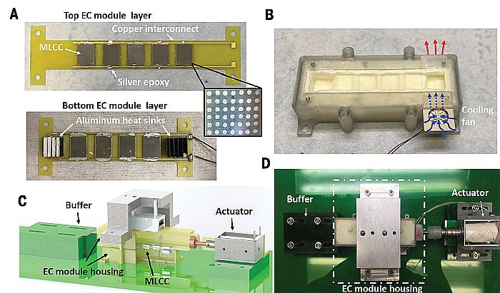
Xerox PARC/Murata EC cooler and key components. (A) Top and bottom EC modules assembled on their plates. The inset shows the copper through-vias behind the MLCCs. (B) Bottom housing structure, including miniature fan and air flow path. (C) Solid model of the cooler assembly. (D) Photograph of the cooler assembly. Click image to enlarge.
The device invented by the research team isn’t fully solid state. It physically moves the capacitors back and forth between hot and cold regions to effect cooling. Specifically, their system includes a pair of stacked modules, each containing EC MLCCs separated by thermal insulating materials. The modules are thermally coupled such that heat can transfer from one capacitor to the next. A mechanism moves the stacked modules laterally relative to one another while an electric field is switched on and off synchronously. The effect is to generate a temperature lift between the two ends of the device that exceeds the MLCC temperature change.
Also key to the design is the use of plates that enhance heat exchange between their layers but are good thermal insulators in the lateral direction. There is nothing exotic about their construction. They are basically glass-reinforced epoxy (FR-4) laminates and copper made via a standard commercial PCB process. In the regions of the plate where the MLCCs attach, plated-copper through-vias serve as thermal shunts for high through-plane thermal conductivity.

Operation of the EC system as described by the Xerox PARC/Murata research team. (A) Relative positions of the EC modules in the two heat transfer stages. (B) The heat flow path. (C) The electric field and actuation timing. (D) Schematic of the Brayton cycle as observed for each MLCC. Click image to enlarge.
The MLCCs are assembled onto the plates to form the top and bottom EC modules containing five and four MLCCs, respectively. The bottom module has an aluminum plate-fin heat sink at each end to facilitate temperature stability. The modules sit in a 3D-printed VeroClear housing filled with polyurethane foam insulation. Besides providing structural support, the housing also minimizes heat leakage. A miniature fan at one end pushes air across the hot-end heat sink.
The top housing connects to a spring-returned single-acting linear solenoid actuator with about a half-inch of stroke. In operation, energizing the actuator draws the top module toward the actuator. When the voltage returns to zero, the solenoid relaxes and a spring returns it to its original position. The EC module housing provides vertical pressure through a set of wheels to keep good thermal contact between the two modules. Control software synchronizes the movement of the top module layer with the application of electric fields to the EC capacitors.
The MLCCs operate via a Brayton cycle, with two zero-voltage and two equal-entropy stages. The scheme uses a 400-V polarizing voltage (equivalent to ~10.5-MV/m electric field) and a 0.2-Hz switching frequency (5-sec period) with about a 50% duty cycle. There are heat sinks at both ends of the device. Over the course of the experiments, heat sink temperature on the hot end rises, while the temperature at the cold end changes in discrete steps as the heater power varies.
The cooling power seen in this small demonstration device is only on the order of hundreds of milliwatts per square centimeter. A more interesting question concerns its COP. Researchers say the EC system COP is a function of the heat collected from the cold side of the device, the additional electrical work associated with charging and discharging the EC capacitor, and the amount of electrical energy recovered each cycle. There’s also mechanical and electrical work required to move the reciprocating system, but that was so small that researchers figured they could safely ignore it. Factoring in all these parameters, they calculated a COP for the experimental setup that is about equal to that of existing Peltier devices.
That result may sound anticlimactic, but there is a key point: The researchers didn’t optimize any of the components in their cobbled-together setup. For example, the copper traces on the PCB were ordinary and conducted a lot of heat. Making them thinner would allow less heat to escape. Ditto for the PCB material. Replacing the ordinary FR-4 board with a polymer material like acrylic would provide more thermal insulation.
And the MLCCs themselves could be improved. Those used in the demo had a form factor optimized only secondarily for thermal behavior. Researchers note MLCCs of the type used in their device have higher thermal conductivity in one orientation than in others. A fix wouldn’t be difficult. There are already other MLCCs commercially available with form factors better suited to use in EC cooling. Even a change to capacitor electrodes with a higher conductivity would help.
Given all the possible improvements, researchers estimate EC-powered A/C using existing PST capacitor material might eventually hit COPs of about 56.4%, making their system competitive with vapor compression cooling. You might say that would be quite a “cool” development. DW
You may also like:


Filed Under: Green engineering • renewable energy • sustainability, Energy management + harvesting, MOTION CONTROL