Though the internet of things is most visible to laymen in consumer devices, the IIoT is massive. The majority of applications are in business, factory, and healthcare settings … and more than a third of the nearly $6 trillion IoT market is in manufacturing.
Connectivity is the basis of all this IIoT — providing the power and data transmission required by controls, devices, machines, and the cloud to execute IIoT functionalities. As we outlined in our six-part series on this topic (at motioncontroltips.com/category/networking-iot) the leading trends here currently include edge computing as well as cloud-connectivity services; components with wireless communications; Ethernet-based networks; open-source programming; software in the form of unifying development environments (UDEs) for large-scale interoperability; and standardized protocols, cables, and connector options.
In this article we do a deep dive on just two IIoT-enabling connectivity standards so essential to today’s motion control systems — the humble M12 connector as well as power over Ethernet (PoE). Then we’ll briefly touch on a third related standard — that of single-pair Ethernet or SPE — as yet another standard to simplify automation.
M12 and M8 connectors — so common on motion components
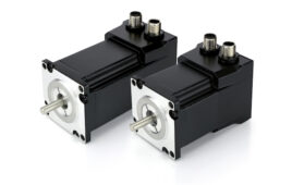
Consider the X-coded M12 connector on NEMA-14 step motors with closed-loop current control from Applied Motion Products. These motors employ power over Ethernet (PoE) connections. In the past getting energy sufficient to power a motor on PoE was challenging … but now that’s changing thanks to higher-power IEEE standards for industrial Ethernet switches. In fact, the 802.3at (PoE+) standard provides 30 W for connected devices — sufficient for running a NEMA-14 step motor at full power. We’ll cover PoE in this article’s next section. But why the M12 connector on this step motor … and what does the “X-coded” designation mean?
Recall that M8 and M12 and connectors are round cable terminations that securely connect automation devices to larger systems as well as common fieldbus networks. They dramatically trim installation time when compared to hardwired designs of yore and can even eliminate the need to hire electricians to install the automated machinery.
Ethernet standards are ubiquitous — right down to their RJ45 socket connectors. While transformers in these RJ45 sockets are common, they’re rare in rugged M12 connectors. Now, HARTING M12 Magnetics includes M12 sockets with transformers to avoid the problem of needing electrical components next to the socket on the connected circuit board. That saves space and cost — and boosts reliability: Conductor tracks can be made lighter and more direct because they don’t have to be arranged around many different components. Plus these connectors are more reliable than combinations of sockets and transformers made by different manufacturers. M12 Magnetics interfaces are capable of 10Gbit and max PoE+ for reliable power and data transmission.
It’s now difficult to imagine the wiring of automated systems before the advent of cordsets and connectors: After all, all sensors and actuators had to be hardwired via pre-attached wiring … often times unjacketed. These conductors required that an electrician fish them through conduit into controls. Upon some component failure, all component wiring had to be disconnected and pulled out — and then rewired by an electrician. The risk of faulty wiring necessitated expert testing before startup. Refer to Design World sister site www.connectortips.com for more on this topic.
M8 and M12 connectors on jacketed cable avoid these complicated routines. The connectors trace their origins to the 1982 release of a proprietary 7⁄8 in. three-pin connector with a free-spinning outer housing called a coupling nut. Just like most of today’s M8 and M12 connectors, this design’s outer coupling nut screwed down onto the male receptacles of devices and equipment for a maximally reliable connection of cable conductors — as well as mechanical shielding of dust and fluids. M12 connectors were introduced a few years later and quickly became a dominant standard. The name M12 refers to the standard metric M12 thread (12 mm in diameter) of this connector’s coupling nut. The smaller M8 connectors — which came a few years later in 1989 — are also named for the metric thread of their coupling nuts … in this case a coarser M8 thread on a major diameter of 8 mm.
Today, M8 connectors join industrial sensors actuators, switches, PLCs, and I/O to various automated systems. In contrast, M12 connectors are used in a wider array of factory automation, test and measurement, food and beverage, and robotics applications. They come with three or four pins (as in initial versions to market — with the latter for advanced sensors and actuators) as well as five, six, eight, or 12 pins. They excel in harsh environments subject to washdown and corrosive substances … and in fact, it’s fairly common to see M12 connectors with IP65, IP67, IP68, and IP69K ratings. These connectors stay watertight even when submerged. That’s one reason they’re so common in food and beverage, rubber and plastic, and textile and printing applications.

MA58H absolute encoders from Encoder Products Co. are heavy-duty multi-turn hollow-bore absolute encoders. They work from -40° C to 85° C and are rated to IP65 on the shaft, with the balance of the unit rated to IP67. Notice the threaded connection at the top of the encoders for standard M12 connectors.
Most sensors and power applications require three and four-pin M12 arrangements. PROFINET and Ethernet use four and eight-pin counts … while most CANbus and DeviceNet connections use four and five-pin counts. 12 pins are necessary for certain modes of signal transmission.

M8 and M12 connectors were first adopted by the automotive industry as a better alternative to hardwiring or relying on more delicate connector types. Today they’re used in all automated industries. Shown here are two M12 connector options for MA58H absolute encoders from Encoder Products Co.
M12 connector coding is a system of standardized mating and shielding geometry to ensure the many variations of the connector type are properly applied. For example, X-coded connectors (mentioned earlier in our step-motor PoE example) are a newer eight-pin option to meet CAT6A requirements for data transmission to 10 Gb/sec. Other common key (coding) variations are:
- A coded M12 connectors for sensors, dc power and 1 Gbit Ethernet
- B coded M12 connectors for PROFIBUS
- C coded (dual keyway) M12 connectors for ac power to actuators and sensors
- D coded four-pin M12 connectors for 100 Mbit Ethernet
- S coded M12 connectors (to supersede C-coded connections) for ac power
- T coded M12 connectors (which will eventually replace A-coded connections) for dc power
A, B, and D connectors are most prevalent, as they’re the original M12 connector variations. That said, X-coded connectors are increasingly common for high-speed industrial Ethernet and are replacing A and D-coded M12 connectors for Ethernet applications. Other newer M12 connectors include K-coded connectors for ac power and L-coded connectors for PROFINET dc power. Refer to Design World sister site www.connectortips.com for more on this topic.
The design of M12 connectors (straight and right angle) are standardized under IEC 61076-2-101. Both PVC and PUR-jacketed cable pairs well with M12 connectors; myriad choices allow full customization of cordsets. Options include shielded and unshielded cable and connectors; armored cable; and stainless-steel coupling nuts and other elements.
Another standardized connectivity option — power over Ethernet (PoE)
Power over Ethernet (PoE) is a standardized networking arrangement employing twisted pair- Cat5e, Cat6, and Cat6a Ethernet conductors to transmit data (with increasing levels of protection against signal noise) as well as electric power.

Servo feedback cable from LAPP called ETHERLINE SERVO DQ FD P Cat.5e cable works with open SIEMENS DRIVE-CLiQ system interface for SIEMENS SINAMICS-S120 drive systems. 85% copper-braiding coverage ensure electromagnetic compatibility.
Defined by the IEEE, PoE versions include those for data transmissions of 10, 100, and 1,000 Mb/sec as well as electrical power transmissions of:
- 15 W for IEEE 802.3af Type 1 devices
- 30 W for IEEE 802.3at Type 2 devices
- 60 W for IEEE 802.3bt Type 3 devices
- 90 W for IEEE 802.3bt Type 4 devices
Both the circa-2003 IEEE 802.3af and newer 802.3at (PoE+) standards along with the higher-power 802.3bt standards (including 60-W “ultra” UPoE) govern the specifics of the cabling and components for such connectivity functions. So PoE is mostly associated with sensors, cameras, and other feedback devices. However, 802.3at PoE+ (and what are called Type 2 devices accepting power from PoE+) is currently seeing the most rapid adoption in the motion-control space for its ability to power actuators. This aforementioned 802.3at standard is particularly relevant to moderately sized motion-control applications, as it defines systems with wattages sufficient to supply full power to electric motors (in this context, PoE powered devices or PDs) used in the actuation of motion axes.

This browser-configurable Opto 22 groov RIO I/O supports IIoT functionality with wired switches and sensors connections to Ethernet networks, software, and cloud platforms. The I/O eliminates the need for PLCs, PACs, or PCs to communicate sensor data … and can mount in hazardous locations without a power supply — because power over Ethernet (PoE) provides both power and data connectivity.

Eliminating the need for an ac power source is another PoE benefit at the remotest of equipment reaches … sans potentially dangerous electrical connections that would otherwise be necessary. In addition, PoE components impart IIoT functionality by allowing physical reconfiguration with connection and disconnection of components at the system switches (in stark contrast to the hassles of hardwiring) to complement the reconfigurability made possible with today’s UDEs and other software.
There are some caveats: For each switch or hub in a PoE system, there is a power budget — the wattage of the switch divided by the number of used ports. In addition, any installation with non-PoE components (and setup for separate power and data conductors) necessitates one of two subcomponents:
- An injector: Often used in setups where PoE field devices are added to existing systems, these send power to PoE-compliant components accepting data through existing non-POE switches. In fact, PoE injectors are a cost-effective alternative to buying new switches to accommodate PoE components having modest power requirements.
- A splitter: These split power and data to separate conductors to allow connectivity with components noncompliant with PoE.
One final caveat: PoE without supplementation can only transmit signals over 100-m stretches off a given switch or hub … and compensatory power supplies as well as (data signal) extenders may be necessary on installations with many PoE devices.

ETHERLINE ACCESS PROFINET switches from LAPP are configurable via a web interface. They help where high transmission rates are required over long distances … and have RJ45 ports as well as small form-factor pluggable (SFP) ports for fiber-optic cables and fast Gigabit Ethernet. Some convert the light signals of fiber optics into electrical signals for 100 Mbit/sec or 1 Gbit/sec and single-mode or multi-mode transmission. Otherwise an ETHERLINE ACCESS U04TP01T switch in this line (ruggedized for mounting near field devices) has four RJ45 ports with Power over Ethernet (PoE) and one port for fast Ethernet. Recall that unmanaged Ethernet switches are cost-effective points of field-device connectivity. They often work as can redundant power inputs and support the plug-and-run functionalities of smart devices. In contrast, managed Ethernet switches actively monitor and troubleshoot the network and its traffic … and act as an access point for other interfaces as well as plant personnel to investigate and adjust machine settings.
Yet another new standard — single-pair Ethernet (SPE)
So far we’ve detailed uses of standard four-pair (eight conductor) Ethernet for data connectivity and the relatively new adoption of PoE. Now another Ethernet standard called single-pair Ethernet (SPE) aims to overtake the mishmash of fieldbuses on the market to simplify and improve the connectivity of field devices and controls … and deliver on the potential of end-to-end industrial Ethernet protocols.
SPE addresses the 100-m limitation of standard Ethernet mentioned above with the potential for runs to 1 km … which could prove quite useful in very large plants or automated settings. SPE cabling is also about a quarter the diameter (and weight) of traditional Ethernet cable … which could prove quite useful where pieces of machinery have very tightly spaced banks of field devices. Defined by the IEEE 802.3cg 10 Mb/sec standard, SPE is incapable of standard four-pair Ethernet data rates … though the 1 Gb/sec so useful in industrial settings is possible — and SPE maintains the built-in data security of all IEEE 802.3 standards.
Note that PoE and SPE aren’t mutually exclusive: SPE can transmit power and data by leveraging existing PoE standards in a power over data line (PoDL) setup. Power distribution techniques are standardized for 10 Mb/sec twisted-pair conductors with wattages comparable to the IEEE 802.3af 15-W standard and beyond.

A newer Ethernet standard called single-pair Ethernet (SPE) aims to supersede the industry’s mishmash of fieldbuses to simplify and improve the connectivity of field devices and controls … and deliver on the potential of end-to-end industrial Ethernet protocols. Relatively high transmission rates and long cable lengths complement power over data line (PoDL) operation. Image via HELUKABEL courtesy of the SPE Industrial Partner Network
Filed Under: Factory automation, CONNECTIVITY • fieldbuses • networks, Motion Control Tips