Thermal management of electronic systems is no longer something you can deal with by installing lots of heatsinks and fans, and crossing your fingers. If you’re building high-performance products, and you don’t want them to overheat or burn-up in use, you need to actually engineer their thermal performance.
It’s in the nature of electronics to get hot. It’s also in their nature to do it unevenly, and in ways that are difficult to manage. Semiconductor devices work best when cold, and must be de-rated when they’re hot. Overheating causes chips to fail prematurely. The higher the chip temperature, the earlier and more certain the failure.
On the average, IC power dissipation is going up, along with PCB densities and component counts. Mentor Graphics, which hosts an annual design competition, has seen the complexity and density of submissions soar, to an average of over 2000 components, packed into 58 square inches. If any one of those components fails, the product fails.
Thermal management is not just a matter of over-engineering to handle the maximum power dissipation of critical components. It requires actually understanding the thermal dynamics of the system, including environmental factors. The only way to do this is through simulation.
Complexities of simulation
Thermal simulation is, in a general sense, a well understood discipline—but there are complications in electronic systems that make it much more of a challenge.
Electronic equipment comprises assemblies of solid objects including PCBs, electronics packages and devices, cabling, fans, heatsinks, and more. The thermal characteristics of these assemblies is a function of convective transport by air flow, complicated by the narrow regions between objects, as well as conduction within the objects, complicated by the objects’ complex internal structures.
There are significant differences in scale between the size of a physical product, and the size of the internal components and circuitry. Often, the scale disparity can range from microns to meters, requiring the use of behavior models in cases where it’s not practical to represent geometry directly in the simulation.
Properly modeling an electronic system requires having quite a bit of information, including component thermal data, power dissipation, material properties, layer thicknesses, and interface resistances. Often, some of this information is either lacking, or low quality.
The combination of these factors—large numbers of components, big scale disparities, and missing data—make thermal simulation of electronic devices a fairly challenging affair. But it’s complicated even further by the typical design workflows in which it must exist.

The traditional way
A typical workflow for thermal simulation of electronic systems often looks something like this: The electronic designer and the mechanical designer both work independently, exchanging only information on form factors and interfaces. When they’re both done with their work, they each send their data to an analyst, in whatever exported form the analyst requests. A few weeks later, the analyst sends them back a stack of colorful images that show whether they have a problem. They then add heatsinks, ducting, and whatever easy fixes that can be added at that late stage of the process. If the problem is serious, they might push the schedule back, so they can make more aggressive fixes.
While I’m being a bit wry in my description, there’s more truth to it than not. Mechanical and electronic design generally run on disparate workflows. The process of exporting design data from the electronic design automation (EDA) and mechanical design automation (MDA) systems, gathering missing data, building the analysis models, then running (and verifying) thermal simulations is time consuming and difficult.
Historically, thermal simulation of electronic systems has been the domain of expert analysts, with specialized knowledge of thermal design and CFD techniques. Most often, it is done later in the product development process, when mechanical and electrical designs are largely complete.
A better way
Doing thermal simulation late is better than not doing it at all, but it’s not nearly as good as doing it earlier, when the feedback it provides can be incorporated into the design with minimal cost. Yet, making this change is not as simple as just deciding it needs to be done.
Existing tools for thermal simulation—whether general purpose, or optimized for electronic systems—don’t lend themselves to use early in the development process. This is not intentional; it’s just an artifact of how those tools were created and developed over time.
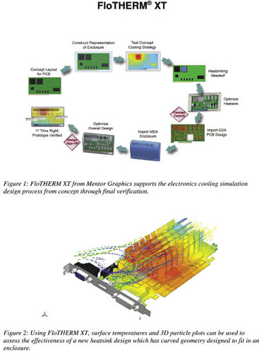
Mentor Graphics recently released FloTHERM XT, a tool for thermal simulation of electronic systems. Where it differs from its predecessor, FloTHERM (without the “XT”), is in being tuned for use throughout the product development process, starting with conceptual design.
One of the important keys to creating early simulation software is in making it usable by design engineers, as well as expert analysts. This is not about “dumbing down,” but is rather about refining, streamlining, and building more intelligence into the product.
Integration with the EDA and MDA workflows is the starting point for optimization. In the electrical realm, Mentor Graphics was able to provide a tight-integration with their EDA tools—which happen to be among the most popular and widely used in industry. In the mechanical realm, were able to use technology from their FloEFD CFD product, which has tight integration to major CAD applications, and is designed to make model simplification and clean-up a (mostly) automatic process. In both realms, FloTHERM XT is able to cleanly sync information, as the models are updated and refined.
One of the important optimizations in FloTHERM XT is in meshing. It uses an octree, or immersed boundary, method that works semi-automatically, with the option to do manual mesh adjustments.
FloTHERM XT’s solver is tuned specifically for electronic systems. For example, in most electronic applications, turbulence is less important than power dissipation, materials, flow rates, or interface resistance. Yet, because there are cases where turbulence can be a source of concern, the program provides options for laminar, transitional and turbulent flows—limiting the type of models, to avoid confusion.
Early thermal simulation
The benefits of early thermal simulation of electronic systems are pretty compelling. By simulating during the conceptual stage of a program, it’s possible to make informed decisions about design alternatives, and ultimately, create better products. While FloTHERM XT is not cheap (about the price of a nice car, to give a sense of scale), it’s easy to integrate into existing EDA/MDA workflows, and is likely to pay for itself rather quickly. If it happens to catch an overheating problem that you might have otherwise missed (and saves you from an expensive recall, or unexpected warranty expense), it could pay for itself the first time you use it.
Mentor Graphics
www.mentor.com
Filed Under: Software • 3D CAD, Sensors (temperature)

Tell Us What You Think!