In part 1 of this article, we discussed various differentiated industrial system applications using capacitive touch technology. These included capacitive liquid level sensing, tactile feedback and indicators, smart keyless lock door entry, and design considerations for added security. We have also covered how to lower the cost of these designs. In part 2, we will cover more industrial applications using capacitive touch technology such as special gestures, proximity X-Y gestures over an area, detection of capacitive objects, and automation and industrial design challenges in harsh operating environments.
Special Gestures:
One of the key advantages of capacitive touch technology is its ability to recognize gestures and take action based on the type of gesture. Gesture recognition allows multiplexed functionality for a given sensor based on the input gesture. It also makes the system efficient from an ergonomics standpoint. There are a wide range of gestures available for use, including swipe up, swipe down, flick up, flick down, single tab, double tab, long press, single finger, 2-finger gestures, and proximity-gestures, among others. This enables integration of multiple features through a given sensor.
As an example, today’s business phones such as VOIP phones and video conferencing control units use gestures to integrate many demanding features as listed below:
- Volume control
- Select between PSTN/VOIP
- Access voice mail
- Caller IDs, Call history
- Dynamically mute/unmute the phone during the conference
- Control the projectors
- Control the lightings of the room, etc.,
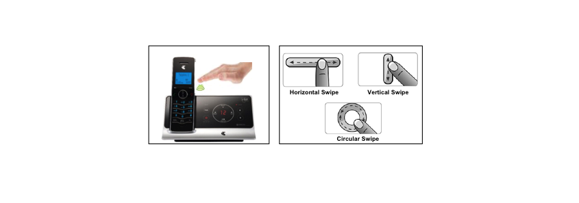
Figure 1: An example of Gesture Application
Capacitive touch sensing technology is a foundation to implement gestures and improve the business user experience and aesthetics on the phone. Let us explore how fundamentally these gestures are implemented in capacitive touch technology. There are two basic types of gestures when it come to the physical implementation level:
- Proximity X-Y gestures over an area
- Touch gestures on a capacitive sensor (e.g. button or slider)
Proximity X-Y gestures over an area: X-Y gestures over an area (e.g. Display LCD) are essentially implemented using a capacitive proximity sensor that detects the gesture. Gesture detection is the technique of interpreting human body movements and providing gesture-type information to the device. Proximity sensors based on capacitive sensing can be used in these applications to detect gestures without any physical contact between the user and the device. Figure 2 shows an example of an implementation of phone gesture detection where proximity sensors are placed across an area to track the X-Y position of a complete pan movement across this area.

Figure2: Proximity Sensor Layout
Note that reliable gesture detection based on capacitive proximity sensing requires a large proximity-sensing distance. Choosing the right type of proximity sensor, sensor size, and sensor placement plays an important role in implementing a reliable gesture detection system. For more detailed design guidelines to implement proximity sensing, see Proximity Sensing with Capacitive Touch Technology and The Capacitive Sensing Design Guide.
Touch gestures on a capacitive sensor: Processing of capacitive touch gestures is done by firmware-based intelligence that tracks hand movement across multiple sensor elements. The construction of these sensor elements can form a slider, touch wheel, or any other pattern, depending upon the application’s UI requirement. One such example of a capacitive sensor pattern is shown in Figure 3. Here there are 13 sensors constructed together to detect multiple gestures such as swipe left, swipe right, swipe up, swipe down, clockwise swipe, and counter-clockwise swipe. In addition to these gestures, a Gesture Pad can be used to implement the functionality of an analog joystick. On top of these, an individual sensor can also be used as a standalone button. This gives designers the flexibility to implements various business phone features using capacitive touch sensing in single system. Since all these features can be implemented using a single MCU, the cost of the system is also minimized without having to compromise functionality.
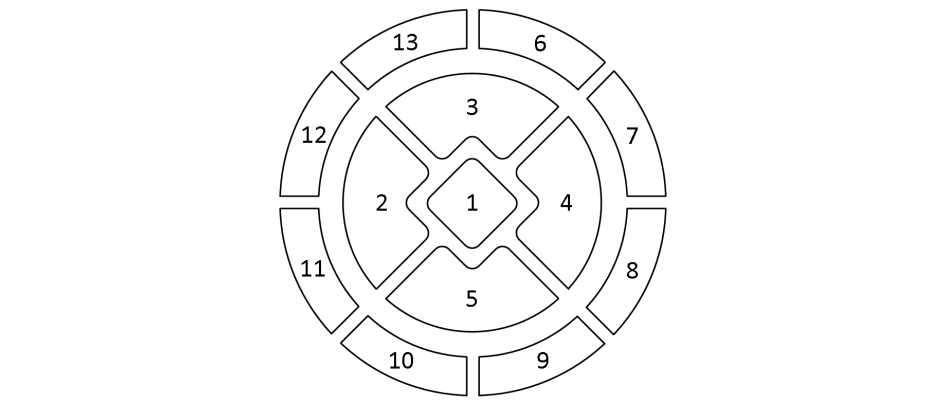
Figure 3: An example of Capacitive Gesture Pattern
Detection of Capacitive Objects & Automation:
There are myriad use cases in industrial machines to detect the presence of an object. Whether the system needs to detect the presence of an object passing by on a conveyor, the closure of a gate, or the position of a machine part during an a particular manufacturing operation, object detection is a staple of the automation industry.
There are many object sensing technologies, including simple mechanical switches and inductive, capacitive, ultrasonic, and photoelectric sensors. The most basic sensor is a limit switch. This is an electromechanical device used to detect the presence or absence of an object. The switch operates its set of contacts when its actuator comes into physical contact with the sensed object. Actuator styles offer an application–specific means of contact – rollers, levers, springs, wands, plungers, etc. However, since these types of sensors consist of moving parts, they are prone to wear and damage. In addition, making physical contact with the sensed object is not always desirable or possible. Capacitive object detection offers a touchless alternative that gives numerous advantages over other techniques in terms of lower system cost and greater feature integration.
A capacitive object detection model for moving objects is shown in Figure 4. Capacitive proximity sensors can detect up to 30 cm reliability. In the case of wide conveyers, two capacitive proximity sensors (one on either side) can be used to increase the detection range. A simple self-capacitive sensing system is sufficient to implement object detection. Typically such a system consists of two plates: one is the sensor electrode connected to the MCU and the other plate is the object itself within the electrical field. As and when the object comes within the proximity of the electrical field, it changes the capacitance seen by the sensor electrode.
One advantage of capacitive proximity sensing is that it can detect a wide variety of conductive materials such as metal, water, etc. Notably, neither object color nor surface reflectivity influence measurement range. Another key strength of capacitive sensors is their ability to detect hidden objects such as the contents of a sealed box. Capacitive sensors can tune out non-metallic container walls and detect different levels of solids or liquids. This capability is particularly useful in applications such as package inspection or liquid-level control where product quality control or process monitoring is not possible by any other means. In short, capacitive sensor technology is extremely effective with many target types for short sensing range.
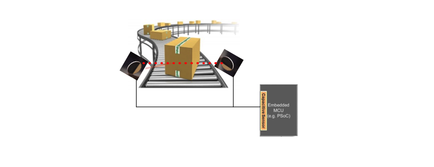
Figure 4: Capacitive Object Detection System
The high level of integration of MCUs for capacitive object detection is significant for automation applications, centralized remote control, report generation, and even wireless IoT nodes. In addition, these MCUs can perform fast computations on the data detected to generate various reports and communicate this data to the cloud via wireless links like Bluetooth Low Energy (BLE).
Industrial design challenges in harsh environments:
System design in industrial harsh environments imposes many challenges since the system is expected to work reliably in dust, water, mist, ice, moisture, humidity changes, extreme temperatures, at high-speed, and often with gloved hands. Capacitive touch applications can be designed to withstand each of these challenges.
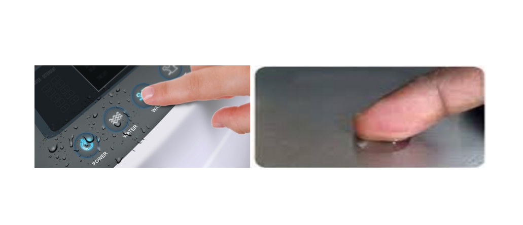
Figure 5: Capacitive Touch in Wet Environment
Water tolerance: Water tolerance or liquid tolerance is a key requirement for industrial capacitive touch systems (see Figure 5). Water tolerance ensures two things: the ability to detect and reject water to prevent a false touch and the ability to detect human touch in the presence of water. This needs special care in design as a simple capacitive touch system may trigger false touches due to the presence of water or liquid. Fundamentally, there are two approaches to address water tolerant design requirements. The first method is to implement a shield electrode which ensures the reliable detection of touch ON / OFF even in the presence of water droplets. The second method is to implement a guard sensor in which a dummy sensor detects the flow of water and disables other (actual button) sensors in the system to prevent false touch, as shown in Figure 6.
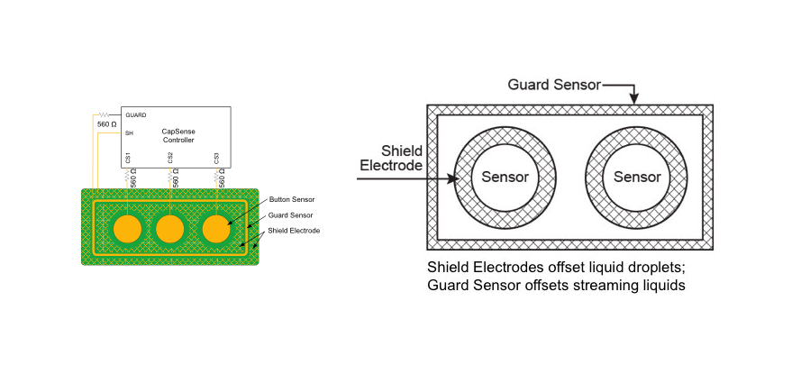
Figure 6: Capacitive Water Tolerance Architecture
Shield Electrode: The driven-shield signal is a buffered version of the sensor-switching signal (see Figure 70. The driven-shield signal has the same amplitude, frequency, and phase as that of the sensor-switching signal. The buffer provides sufficient current for the driven-shield signal to drive the high parasitic capacitance of the hatch fill on the PCB. When the hatch fill surrounding the sensor is connected to the driven-shield signal, it is referred to as the Shield Electrode. As the shield electrode is driven with a voltage which is the same as the sensor-switching signal, the capacitance added by a liquid droplet when it falls on the touch surface will be nullified.
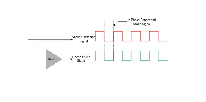
Figure 7: Driven-Shield Signal
Guard Sensor: Though a shield electrode is very effective method for small water droplets, the effect of the shield can be completely masked by larger streams of water. A guard sensor is used in such scenarios (see Figure 6). A guard sensor is a dummy sensor of copper trace around the actual sensors in the system. It detects larger flows of water and feeds this information to the CPU. Upon the detection of the stream of water, the firmware logic in the CPU disables the other actual sensors in the system to prevent a false touch from being sensed. The limitation of this method is that a finger touch cannot be detected as long as the water stream exists.
Extreme temperatures: Industrial designs have to work in harsh operating environments such as extreme temperatures. Capacitive touch sensing circuits are generally sensitive to environmental (i.e., temperature, humidity, etc.) changes. The raw count (digital equivalent of input capacitance) usually varies with changes in environmental conditions and could trigger false touch at times. This requires proper compensation for environmental conditions to ensure reliable operation. Usually compensation is implemented in both hardware and firmware. Hardware compensation auto-calibrates the sensing circuit by varying the input current according to changes in temperature to keep the output raw count constant. This takes care to set the right output at every power on reset, irrespective of the temperature.
On the other side, firmware compensation takes care of run-time temperature changes. The raw count value of a sensor may vary gradually due to changes in the environment such as extreme temperature and humidity. Therefore, the raw count is low-pass filtered in firmware to create a new count value known as a baseline that keeps track of and compensates for gradual changes in raw count. The baseline is less sensitive to sudden changes in the raw count caused by a touch. Therefore, the baseline value provides a reference level for computing the signals (see below). Figure 8 shows the relationship between raw count, baseline, and signal. These techniques ensure reliable operation of capacitive touch sensors in harsh conditions.
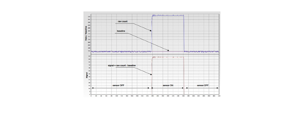
Figure 8: Concept of Raw Count, Baseline & Signal
Gloved hand: It is common for workers in industrial applications to operate machines with gloves, such as latex gloves in medical applications and leather gloves in cold weather conditions. Hence, capacitive touch sensors in industrial designs have to account for these conditions. However, implementing gloved touch is not easy. There are two common problems in gloved touch implementations: poor signal acquisition when a user wears a glove due to low input capacitance and a hovering effect when a user touches with a bare finger due to highly sensitive sensors. These problems can be eliminated with proper design considerations taken at both the firmware and hardware levels. On the firmware side, individual thresholds can be used to differentiate the signal between gloved hand and bare hand. Sensor designs can also be optimized to individually sense gloved hands and bare hands at the hardware layer. With these considerations, a capacitive touch system for industrial applications can be optimized to work seamlessly in conditions where user may or may not be wearing gloves.
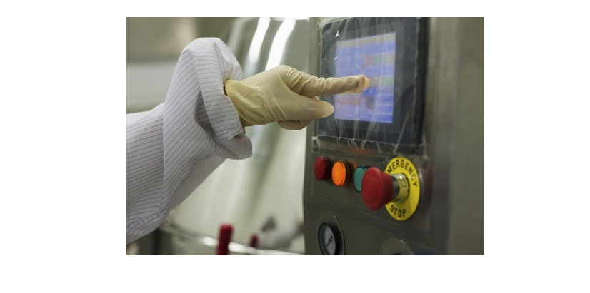
Figure 9: Capacitive Touch Application using Gloved Hand
References:
- Getting Started with CapSense®
- PSoC®4 -Capacitive Liquid-Level Sensing
- Getting Started with PSoC® 4 BLE
- PSoC 4 BLE – Designing BLE Applications
- PSoC® 4 CapSense® Design Guide
- PSoC 4 BLE Datasheet (PSoC® 4: PSoC 4XX8 BLE 4.2 Family Datasheet)
- AN210772 – Energy Calculation for Energy Harvesting with S6AE101A, S6AE102A, and S6AE103A
- AN79953 – Getting Started with PSoC® 4
- AN204361 – Hybrid Application using Energy Harvesting PMIC
- CE202479 – Code Example for liquid-level sensing
- PSoC 101 Training series
About the Authors
Jaya Kathuria works as an Applications Manager at Cypress Semiconductor Corporation where she is managing the Embedded Applications Group and Solutions Development using the PSoC platform. She has 11+ years of experience in Semiconductor Industry. She earned executive management credential from IIM, Bangalore and holds BS in Electronics Engineering from the Kurukshetra University. Jaya can be reached at [email protected].
Anbarasu Samiappan is a Senior Applications Manager at Cypress Semiconductor. He is managing PSoC Embedded Systems Group including Customer Technical Support and System validation functions. He is a PMI certified Project Management Professional, Gold medalist Electronics Engineering Graduate from Anna University and earned General Management credential from IIM, Bangalore. He has 19+ years industry experience. Anba can be reached at [email protected].
Filed Under: Energy management + harvesting, Rapid prototyping