The term linear guide covers several categories of products, from plain bearings to ball bushings and recirculating roller bearings. To compound the potential for confusion, many terms are used interchangeably, or are so generic (take linear guide for example) that they could refer to any one of several different products. And this doesn’t apply to just product descriptions; design types and technical features are, in many cases, referred to by different names depending on the manufacturer. To help cut through the confusion, below is a list of terms that are used to identify, describe, and specify linear guides.
*This glossary focuses on recirculating linear guides (ball and roller), since plain bearing guides have less variability in their terminology and specification.
Product types
There are two main types of recirculating ball guides: one that rides on round shafts and one that rides on profiled rails. Because both types are based on recirculating balls, the terminology used to refer to them is very similar and often overlaps. Here’s a breakdown of the most common terms that are used for each one:
Round shaft recirculating ball guides: also referred to as linear bushings, ball bushings, bushes, or the generic “ball bearing.”
While “ball bearing” is the least descriptive, it is one of the most commonly used terms, and when used in the context of linear guides, it is probably referring to a round shaft bearing. Round shaft versions are the original linear recirculating ball guides and are still widely used in applications with lower loads and forces or where the environment is extremely harsh.
Profiled rail recirculating ball guides: also referred to as guide rails, linear guides, LM guides, or profiled rails.
In these systems, the guideway has a generally square shape and is specially machined so that the load-bearing elements (either balls or rollers) run in tracks on the rail. Profiled rail recirculating guides have higher load capacities and greater rigidity than round shaft versions and are used in all types of applications, from simple pick-and-place to semiconductor equipment and machine tools.
Technical specifications
Load capacity is the most basic specification of any linear guide. Recirculating linear guides can withstand both pure forces and moment (overhung) loads. But they are rated for two different types of load capacity: static and dynamic.
Static load capacity, denoted C0, is the load or moment at which permanent deformation of the raceway equals 0.0001 times (0.01 percent) of the ball or roller diameter.
Dynamic load capacity, C, is the constant load, oriented normal to the load-bearing surface, at which 90 percent of a sample will operate for a defined travel distance. Dynamic load capacity is used to calculate theoretical bearing life.
Accuracy is one of the defining characteristics of a profiled rail guide assembly. The accuracy class of a profiled rail and bearing is assigned based on five different specifications:
-Height tolerance of the rail-carriage assembly
-Permissible difference in height among multiple carriages on the same rail
-Width tolerance of the rail-carriage assembly
-Permissible difference in width of multiple carriages on the same rail
-Parallelism between the reference surfaces of the rail and the carriage
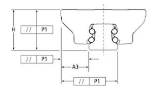
Profiled linear guide accuracy class specifies height, width, and parallelism.
Image credit: Thomson Linear
Preload is another important characteristic of profiled rail guide assemblies, since it determines how much clearance (or lack thereof) will be present between the bearing block and guide rail. Preload is induced by using balls (or rollers) whose diameter is slightly larger than the distance between the raceways of the bearing block and guide rail. This eliminates the internal clearance between the rail and bearing block and reduces deflection when an external load is applied.
Construction
While bearing construction isn’t a technical specification, it is typically referenced in manufacturers’ catalogs, and the various construction options have a significant affect on performance.
Raceway arrangement refers to where and how the load-bearing balls “sit” on the profiled rail. There are two raceway arrangements: face-to-face and back-to-back.
The face-to-face arrangement is often referred to as the “X” arrangement because the contact lines between the balls and the raceways point inward, making an “X” inside the profiled rail. This arrangement gives the assembly equal load capacity in all directions, but reduces its ability to handle moment loads.
The back-to-back arrangement is also known as the “O” arrangement because the contact lines point outward, making an “O” around the rail. This design gives a longer moment arm and allows the bearing to withstand high moment loads.
Raceway geometry determines the number of contact points between the ball and raceway and affects the bearing block’s friction and load capacity.
Circular arc geometry produces two-point contact between the ball and the raceway. This gives the assembly a lower friction coefficient and smoother running characteristics.

The circular arc design provides two-point contact between the ball and the raceway.
Image credit: Bosch Rexroth
Gothic arch geometry provides four-point contact between the ball and the raceways, resulting in higher moment load capacities but also higher friction.
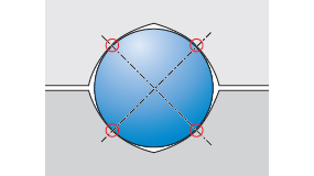
The Gothic arch design provides four-point contact between the ball and the raceway.
Image credit: Bosch Rexroth
Feature image credit: SKF
Filed Under: Linear Motion Tips, Motion control • motor controls


