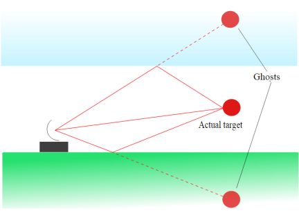
Signal reflection is a problem that arises when the cabling between devices or terminations at either end are substandard. This can happen in copper wire, in traces on a printed circuit board, in optical fiber. It is also a fact of life for wireless communication media where signals reflect from nearby objects and can arrive at a receiver sometime after the main line-of-sight signal.
Characteristic impedance is a property of any two-wire medium as described by Oliver Heaviside in 1886. It is distinctly different from impedance. It is an attribute of transmission lines such as coaxial cable or twin-lead antenna wire. It does not depend upon length. It is determined by the interaction of parallel capacitive reactance and series inductive reactance.
For a medium such as coax to function as a link, its characteristic impedance must be uniform along its entire length. For this reason, manufacturers must institute rigorous quality control programs, to ensure dielectric thickness, conductor size, spacing and similar metrics remain uniform.
For the circuit to work, the impedances of the source and transmission line, including terminations and load, must match. (Intentional mismatching can be introduced for the purpose of attenuation.) Only under these conditions can maximum power transfer take place.
If there is a mismatch anywhere along the line, caused perhaps by a kinked wire or staple driven in too tightly, there will be incomplete power transfer between transmitter and receiver. (In actual practice this may be a two-way affair.) Naturally, the energy must go somewhere, and if it is not dissipated as heat, it is reflected back from the anomaly. In the process there can be data collisions between the information bits traveling in opposite directions. The end result is data corruption and poor performance.
An analogous situation can arise in optical fiber. This medium is a type of waveguide made of a glass or inner core and a cladding of similar material that has a different refractive index.
Light, as postulated by James Clerk Maxwell in his 1865 treatise Dynamical Theory of the Electromagnetic Field, is a form of electromagnetic radiation that is not essentially different from radio waves. It is accompanied by magnetic and electrical fields, which is why a beam of light can be bent by a strong magnet. The difference is that light oscillates at a much higher frequency. The wavelength of violet light, for example, is as short as 380 nm, corresponding to a frequency of 789 THz. Because of the short wavelengths involved, the diameter of the waveguide is much smaller. The width of a waveguide is designed to be of the same order of magnitude as the wave to be guided.
The diameter of the inner core of optical glass fiber ranges between 10 and 600 microns, slightly larger than a human hair. The principle of propagation is the same as in the enormous waveguide consisting of different naturally occurring thermal layers in oceans that convey the low frequency cries of whales thousands of miles.
Light travels through optical fiber, zigzagging from side to side without excessive loss, bouncing off the inner reflective surface of the outer cladding. The optical fiber can be bent provided minimum radius is observed. Multimode optical fiber is fairly easy to install, whereas single mode optical fiber is far more challenging.
The post Basics of EM signal reflections appeared first on Test & Measurement Tips.
![]()
Filed Under: Test & Measurement Tips