By Michael Hoffman, of Dragos and the SANS Technology Institute

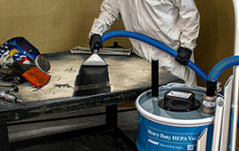
Figure 1: Inlet manifold of expansion joint.
Few industries require more product validation and qualification than the military and aerospace sectors. Before any new technology is approved by the military’s regulatory agencies, they must undergo many levels of technology development, often in a simulated environment. This test environment is designed to push products to their limits to ensure they hold up to real-world demands.
Above all else, these tests must be accurate and reliable, delivering boundary conditions for performance and modeling validation and verification. Engineers cannot guarantee the reliability of their products if the testing equipment itself cannot produce accurate, repeatable results. That is why designing functional test equipment is just as important as the products they test.
TCH Industries, a specialist in custom hose and fittings, experienced this demanding environment firsthand when one of its customers designed an Advanced Propulsion Concepts test facility for the U.S. military. To validate a new concept, the military has to create a custom testing environment. This environment needed to simulate the high altitudes, fluctuating environments, and extreme pressures and temperatures that the concept would face during normal operation. There was an eight-in. inlet system that would deliver air into the propulsion system to allow for reliable thrust output results. Standard bellows expansion joint designs were not feasible, as they would impart a force under the testing conditions.
With the advanced nature of these challenges, the engineers at TCH Industries realized they needed additional resources to offer a complete design. That is why they partnered with Hose Master, a leader in metal hose and bellows expansion joints. Together, the two companies created a custom U-loop expansion joint design that met all of the requirements of the unique testing environment. By creating an expansion joint that would hold up to military-grade functional testing, TCH and Hose Master enabled our military to validate its Advanced Propulsion Concept.
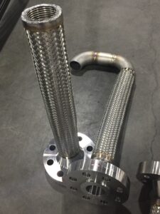
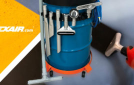
Figure 2: Subassembly of U-loops that join the two manifolds.
The High Demands of Mil-Aero Applications
Functional tests in the military demand more from engines and propulsion systems than in other sectors such as the automotive or commercial aircraft industry. Not only will these engines face challenging environments such as high altitudes and extreme temperatures, but they will also need to perform at top efficiency.
To become viable, the Advanced Propulsion Concept would need to go through tests that would push the design to the extreme limits it would face out in the field. The design would need to face intense conditions such as:
• High pressures up to 750 psi
• A tremendous amount of flow through the eight-inch inlet pipe
• High temperatures up to 1075 degrees Fahrenheit
• Supersonic velocities
• Axial compression up to 1-in.
Most importantly, the test apparatus could not apply additional forces on the load cell. If forces were not properly balanced, it would produce inaccurate performance results.
Design One: The Pressure-Balanced Bellows Expansion Joint
To complete its testing design, the military reached out to TCH to develop a custom expansion joint. The initial design was a pressure-balanced bellows expansion joint. This expansion joint design would eliminate the end thrust forces of the input air by mechanically restraining the forces with equal and opposite force outputs.
However, this caused the system to act like a giant spring due to the compression of the bellows. The system would compress 1-in. due to thermal expansion, which would output tens of 1000s of pounds of spring force from the expansion joint on the test cell.

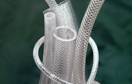
Figure 3: CAD rendering of expansion joint.
Within the bounds of the bellows-style design, there was no way to completely eliminate forces because of the design’s inherent limitations. While it solved the initial problem of unrestrained thrust, it left the massive spring force issue unresolved. This design would create skewed test results because the test fixture would impart force unrelated to the thrust being measured. Upon reviewing the design considerations with the military, the TCH team realized they had to pivot and go through another design iteration.
Understanding the limits of the bellows-style design of the pressure-balanced expansion joint, the engineering team realized they needed to think outside the box.
Together, the design engineers at TCH and Hose Master knew that they needed an entirely different type of solution. A U-Loop Expansion Joint was suggested — Hose Master’s design experts brought it to life.
With direction from TCH, Hose Master developed a custom U-loop manifold design. This design used four U-shaped hose assemblies on the top and four U-shaped hose assemblies on the bottom of the manifold. The manifold design was essentially hose that also acted as an expansion joint, specifically a non-force-inducing expansion joint. All of the forces equaled zero since everything that happened on the top occurred on the bottom, and all lateral forces were contained by the pipe.
Once the custom manifold design was finalized, the two companies went through multiple design iterations to get it right. Iterations include changing the centerline of the hose spacings and changing the branch connections to increase weld efficiencies. These iterations required a high level of collaboration between Hose Master, TCH, and the customer, so that everything could be accounted for.
Creating a new expansion joint for the military’s testing equipment required a higher degree of expertise and a greater product offering than typical hose and expansion joint suppliers can provide. Many traditional expansion joint makers only make bellows-style expansion joints, which would have been a never-ending design struggle to eliminate forces.

Figure 4: Inlet and outlet manifolds capped and ready for shipping (outlet side in the forefront).
Since Hose Master was both a bellows-style expansion joint manufacturer and a metal hose manufacturer, it could use the design constraints of one to turn it into another. Beyond the structure of the design, TCH and Hose Master also had the materials expertise to specify a metal that could stand the 1,075° F temperatures of the testing environment. That is why they chose 316H stainless steel. The higher carbon content of 316H stainless steel makes it particularly useful for applications with elevated temperatures, making it the perfect choice for high-temperature testing. The viability of the final design was proven through tests such as:
• Radiography
• Dye penetrant testing
• Pressure tests
These tests gave the U.S. military peace of mind knowing that the Advanced Propulsion Concept would be validated in a secure and regulated environment.
TCH Industries
tchindustries.com
Filed Under: Aerospace + defense, Hose • wraps + sleeves