Design World

  • Home
  • Technologies
    • 3D CAD
    • Electronics • electrical
    • Fastening & Joining
    • Factory automation
    • Linear Motion
    • Motion Control
    • Test & Measurement
    • Sensors
    • Fluid power
  • Learn
    • Ebooks / Tech Tips
    • Engineering Week
    • Future of Design Engineering
    • MC² Motion Control Classrooms
    • Podcasts
    • Videos
    • Webinars
  • LEAP AWARDS
  • Leadership
    • 2022 Voting
    • 2021 Winners
  • Design Guide Library
  • Resources
    • 3D Cad Models
      • PARTsolutions
      • TraceParts
    • Digital Issues
      • Design World
      • EE World
    • Women in Engineering
  • Supplier Listings

D-sub connectors: Everyone speaks of them incorrectly

By mrowe | May 16, 2022

Share

You probably don’t know it, but you’ve been referring to most D-sub connectors incorrectly for your entire career. Here’s how to get them right, but you’ll be speaking a language that few understand.

D-Subminiature (D-sub) connectors, you find them in consumer PCs, industrial equipment, and even in networking equipment. They’re everywhere and manufactured by many companies. You’ve probably been referring to them incorrectly for years.

DB-25 connectors
Figure 1. Ribbon cables attache to DB-25 connector though use of a press.

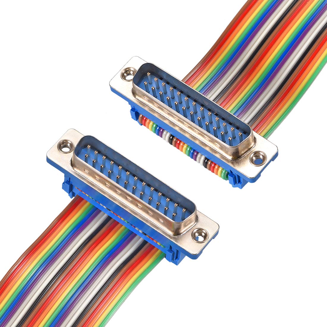
I once worked for a company that manufactured semiconductor process equipment. The Wafertrac moved wafers floating on air from one processing station to another. Each station connected to a dedicated controller board in a chassis through one or more 25-wire ribbon cables (Figure 1). The end of each cable used a DB-25 connector that inserted into the module or controller board. Once inside the module, wires from the ribbon cable then divided, going to other connectors that delivered power, control signals, and sense signals to and from a station.

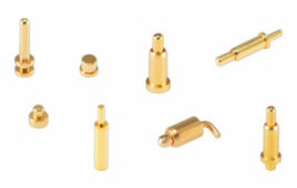
Instead of ribbon cables shown in Fig. 1, some of the I/O cables routed to the modules were shielded multi-wire cables. They carried, for example, power to a motor. As a result, we went to a DB connector such as the one shown in Figure 2, which has three high-current pins. Typically, the A3 line on the left delivers the power, with two return lines to minimize return-line impedance.

DB-25 power
Figure 2. This DB-25 pin configuration uses fewer I/O pins but add three power pins.

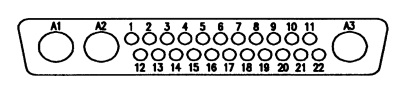
The connectors in Figs. 1 and 2 are “DB” connectors. Why? Because the shell outline looks something like a letter “D.” What about the next letter? Here’s where things do wrong.

The second letter stands for the size of the connector shell. If that’s the case, then why do we often refer to all the D-sub connectors with “DB” as in DB-25, DB-9, and so on? We shouldn’t, but we do.

PC connectors
Figure 3. Desktop computers used to have a DB-25 socket connector for printers, a DE-9 plug for a serial port, and a DE-15 socket for a VGA monitor.

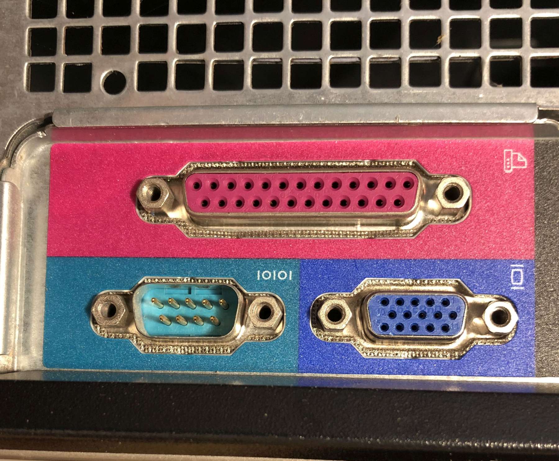
Look at the rear panel of an older desktop PC in Figure 3. Here, we have three D-subs with three pin configurations and two sizes. You might be tempted to refer to these connectors as DB-9, DB-15, and DB-25. Only the DB-25 is correct. The other two are DE-9 (used for a serial port) and DE-15 (for VGA video). There are five sizes in all, ranging in pins from 9 to 78. The table lays out the connector configuration for connectors that don’t use the large power pins. You can find many online pages that specify these connectors in detail. One such document is “D-Subminiture Talking Dog page” from PEI-Genesis.

Designation Number of pins (normal or high-density) Example configuration
DA 15 or 26
DB 25 or 44
DC 37 or 62
DD 50 or 78
DE 9 or 15
Figure 4. This DA-15 cable connector contains solder cups for attaching cable wires.

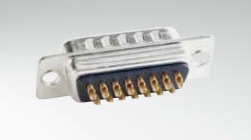
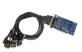
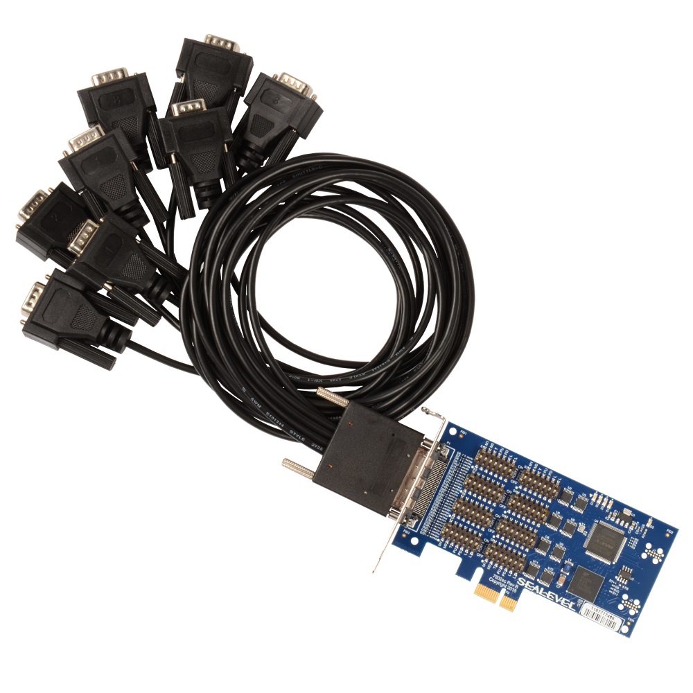
D-sub connectors attach to cables and to boards. Figure 4 shows a 15-pin solder-cup version of a D-Sub connector while the ribbon cables in Fig. 1 connect by being pressed into the connector pins. Figure 5 shows a board that inserts into a PCIe slot to add eight RS-232/485 ports to a desktop computer. The board’s specification page refers to the eight 9-pin cable connectors as “DB9.” Sorry, but it’s DE9. The “E” side connector, mostly used for 9-pin serial and 15-pin VGA, was developed last. Thus, it’s out of sequence relative to the others.

Sealevel systems serial port board
Figure 5. This serial-port board from Sealevel Systems adds eight ports to a desktop PC. The data sheet refers to the eight DE-9 cable connectors as DB9.

Filed Under: Connector Tips
Tagged With: Sealevel Systems
 

Related Articles Read More >

RF connectors cover DC to 90 GHz
binder USA introduces M12 K- and L-coded connectors for North America
Why connector return loss causes signal problems
Driving standards: The latest liquid-cooling cables and connectors for data centers

DESIGN GUIDE LIBRARY

“motion

Enews Sign Up

Motion Control Classroom

Design World Digital Edition

cover

Browse the most current issue of Design World and back issues in an easy to use high quality format. Clip, share and download with the leading design engineering magazine today.

EDABoard the Forum for Electronics

Top global problem solving EE forum covering Microcontrollers, DSP, Networking, Analog and Digital Design, RF, Power Electronics, PCB Routing and much more

EDABoard: Forum for electronics

Sponsored Content

  • Renishaw next-generation FORTiS™ enclosed linear encoders offer enhanced metrology and reliability for machine tools
  • WAGO’s smartDESIGNER Online Provides Seamless Progression for Projects
  • Epoxy Certified for UL 1203 Standard
  • The Importance of Industrial Cable Resistance to Chemicals and Oils
  • Optimize, streamline and increase production capacity with pallet-handling conveyor systems
  • Global supply needs drive increased manufacturing footprint development

Design World Podcasts

June 12, 2022
How to avoid over engineering a part
See More >
Engineering Exchange

The Engineering Exchange is a global educational networking community for engineers.

Connect, share, and learn today »

Design World
  • Advertising
  • About us
  • Contact
  • Manage your Design World Subscription
  • Subscribe
  • Design World Digital Network
  • Engineering White Papers
  • LEAP AWARDS

Copyright © 2022 WTWH Media LLC. All Rights Reserved. The material on this site may not be reproduced, distributed, transmitted, cached or otherwise used, except with the prior written permission of WTWH Media
Privacy Policy | Advertising | About Us

Search Design World

  • Home
  • Technologies
    • 3D CAD
    • Electronics • electrical
    • Fastening & Joining
    • Factory automation
    • Linear Motion
    • Motion Control
    • Test & Measurement
    • Sensors
    • Fluid power
  • Learn
    • Ebooks / Tech Tips
    • Engineering Week
    • Future of Design Engineering
    • MC² Motion Control Classrooms
    • Podcasts
    • Videos
    • Webinars
  • LEAP AWARDS
  • Leadership
    • 2022 Voting
    • 2021 Winners
  • Design Guide Library
  • Resources
    • 3D Cad Models
      • PARTsolutions
      • TraceParts
    • Digital Issues
      • Design World
      • EE World
    • Women in Engineering
  • Supplier Listings