By Luke Lecheler
Luke Lecheler is the Communications Coordinator at EtherCAT Technology Group
Volente, Texas
EtherCAT – Ethernet for Control and Automation Technology – is a cost-effective, real-time, international standard that makes Ethernet technologies available at the I/O level.
The introduction of fieldbus technology was a major milestone for the widespread application of PC-based control systems. CPU power has been increasing rapidly, however, the communication speed and performance of traditional fieldbuses have not kept pace, causing bottlenecks that can impede the performance of modern control systems. Many suppliers in the automation industry are now turning to Industrial Ethernet. Ethernet has long been the communication standard in office settings, but is still relatively new at the drive or I/O level – areas that have been dominated by fieldbus systems in the past.

In an EtherCAT network, each slave processes data “on-the-fly”; input data is inserted into telegrams as the frame passes through the node at full speed.
Not all industrial Ethernet types are created equal
Typically, Ethernet protocols require individual Ethernet frames for each device on the network. Because the frames have minimum length requirements, they can only pass small payloads of a few bytes of data per node (typical for I/O devices). The output from this poor use of bandwidth is merely comparable to traditional high-speed fieldbus systems. EtherCAT avoids this limitation.
With EtherCAT, the frame is not received and interpreted with the process data copied at each individual device. Rather, the EtherCAT slave devices read the data specifically addressed to them while the frame passes through the node at full speed. Similarly, input data is inserted as the frame passes through the node at full speed. The process produces a useable data rate of more than 90%.
It also maintains the Ethernet protocol (IEEE 802.3) down to the individual devices on the network, so it does not require an underlying bus. For example, to meet the requirements of a modular device, such as an electronic terminal block, the physical layer in the coupling device can be converted from twisted pair or optical fiber to LVDS, an alternative Ethernet physical layer at the I/O module level. This saves costs when extending modular devices. In addition, EtherCAT offers a flexible topology, accurate synchronization through distributed clocks, high performance, advanced diagnostics, and a safety protocol.

EtherCAT takes full advantage of the available bandwidth. Its useable data rate averages over 90%.
Topology
A typical Ethernet system involves a star topology, which requires switches, as well as the most cable of any topology. However, EtherCAT can be wired as a combination of lines, branches, and stub configurations, which are commonly used in hub and spoke topology. This flexibility lets the network avoid the typical quantity limitations associated with cascaded switches or hubs; and saves costs associated with switches, cables, and power supplies.
Standard, inexpensive Ethernet patch cables that transfer signals in 100BASE-TX mode suit EtherCAT, and for special applications, optical fiber can be added to complement the system.
Synchronization
Accurate synchronization is particularly important in cases where spatially distributed processes require simultaneous actions. An example of this is an application where several servo axes perform simultaneous movements.
EtherCAT takes full advantage of distributed clocks. Distributed aligned clocks have a high degree of tolerance to possible fault-related delays within the communication system.
The standard’s data exchange is based fully on a pure hardware machine. The communication uses a logical and physical ring structure, so the master clock can determine the propagation delay offset to the individual clocks – and vice versa – simply and accurately. The distributed clocks are then adjusted based on this value for a precise network-wide time-base with a jitter of significantly less than 1 µs.
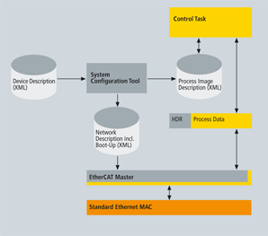
The diagram illustrates the structure of a Master Sample Code EtherCAT system. Configuration tools, implementation services, and support are available from several manufacturers. EtherCAT master sample code is also available for a nominal fee. The software is supplied as source code and contains all master functions including Ethernet-over-EtherCAT. Developers only need to adapt the code, which is designed for a Windows environment, to the specific target hardware and real-time operating system.
Diagnostics
With any fieldbus system, availability and commissioning times depend on diagnostic capability. Faults can only be rectified if they are located unambiguously and detected quickly and accurately. During commissioning, the actual configuration of the nodes, such as drives or I/O terminals, should be checked for consistency with the specified configuration. The topology should also match the configuration. EtherCAT provides built-in topology recognition down to the individual terminals. This verification takes place during system start-up, and automatic reading of the network is possible (configuration upload).
Evaluation of the CRC checksum reliably detects bit faults during the transfer. Apart from broken wire detection and localization, the protocol, physical layer, and topology of the EtherCAT system make it possible for the quality monitoring of each individual transmission segment. The automatic evaluation of the associated error counters enables precise localization of critical network sections. The network detects and locates gradual or changing sources of error such as EMI influences, defective connectors, or cable damage, even if they do not yet overstrain its self-healing capacity.
Safety
Safety-over-EtherCAT is a certified protocol for transferring process data between Safety-over-EtherCAT devices up to SIL 3 (according to IEC 61508). EtherCAT is used as a single-channel communication system for transferring safe and non-safe information. The transport medium is regarded as a “black channel” and is not included in the safety considerations. A safety frame containing the safe process data and the required data backup is included in the process data. This “container” is analyzed in the devices at the application level. Communication remains single-channel.
Easy to implement
The process of implementing an EtherCAT system is straightforward. It requires configuring an EtherCAT master and slave device. The master device sends standard Ethernet frames to a slave device that extracts or inserts data “on-the-fly.” The only hardware requirement of an EtherCAT master is a standard NIC. Plug-in cards are not necessary.
What’s more, EtherCAT masters do not require a dedicated communication processor. EtherCAT systems typically only need one or two frames per cycle for communication with all nodes on the network, so the master puts only a small load on the host CPU. This lets the host CPU easily process the application program.

Slave hardware: FPGA with host CPU. The parallel 8/16-bit microcontroller interface corresponds to conventional interfaces for fieldbus controllers with a DPRAM interface. It suits more complex devices with larger data volumes well.

Slave hardware: FPGA with direct I/O. The 32-bit parallel I/O interface is suitable for the connection of up to 32 digital inputs/outputs, and also for simple sensors or actuators operating with 32 data bits. These devices do not need a host CPU.
Several manufacturers provide EtherCAT slave controllers. The functions of a slave controller can also be implemented cost-effectively on FPGAs. Configurable binary code is available for this purpose. Slave controllers typically feature an internal DPRAM and offer a range of interfaces for accessing this application memory, including the parallel 8/16-bit microcontroller interface, the 32-bit parallel I/O interface, and the SPI (Serial Peripheral Interface). The SPI (Serial Peripheral Interface) is intended particularly for devices with a small process data quantity, such as analog I/O modules, sensors, encoders, or simple drives. This interface is typically used with 8-bit microcontrollers.
Why EtherCAT?
EtherCAT combines the advantages of fieldbus technology with those of Industrial Ethernet. It uses almost the entire bandwidth and reduces costs to a simple FPGA or ASIC connection in the EtherCAT device. Standard components are used where they are in fact standard – in the controller and not in the 2-bit I/O terminal. The standard does not require IP addresses, and because the master controls the configuration using simple algorithms, configuration is automatic.
In automation, it is clearly a trend to use Ethernet at the field level. EtherCAT enables the creation of extremely high-performance machine controls that can exchange many distributed signals with cycle times significantly below 100 µs. Any commercially available PC or controller with an Ethernet port can function as a master.
The EtherCAT Technology Group (ETG) is a global organization of over 700 OEMs, end users, and technology providers that support and promote EtherCAT development and offer further implementation support.
EtherCAT Technology Group (ETG)
www.ethercat.org
The bus is no longer the bottleneck
EtherCAT communication is completely independent of the runtime of protocol stacks, CPU performance, or software implementation. This is because hardware integration in the slave, as well as direct memory access to the network controller in the master, mean complete protocol processing within the hardware. The result is an extremely fast network.
For example, the update time for 1,000 digital I/O, including I/O cycle time, is only 30 µs. This
allows for control designs that were impossible with traditional fieldbus systems. With EtherCAT, the bus system is no longer the bottleneck of the control system.
Master-implementation with one process image
In the case of a PLC with a single process image, the EtherCAT master can cyclically send a single Ethernet frame with the cycle time of the PLC. This is sufficient because the standard only requires that a constant header be added to the process image, and the result transferred to the Ethernet controller. Also, since mapping occurs in the slaves and not the master, the process image is already sorted, which further decreases the burden on the host CPU. It uses less of its processing power than host CPUs in much slower fieldbus systems implemented with active plug-in cards.

:: Design World ::
Filed Under: CONNECTIVITY • fieldbuses • networks, Motion control • motor controls

Tell Us What You Think!