by Christine Klier, PhD
A common difficulty in the simulation of complex fluid flow problems is that not all geometry can be well represented using a single, contiguous grid. This is especially true for the case of relative motion between components. Overset grids can be used to track relative motions with computational efficiency and recent advances in high-performance computational fluid dynamics (CFD) software like STAR-CCM+ have enabled the coupled simulation of multiphase fluid flows and rigid body motions using overlapping overset grids.
A CFD method was developed and applied for the simulation of oil flow in a multiple rotating spur-gear system with emphasis on predicting the flow fields and pressure torques in the gearbox and between intermeshing gear regions. The multiphase flow in this problem was simulated using the Volume of Fluid (VOF) method and the results indicated that the applied CFD method offered a convenient and efficient way to study different oil-filling levels in a gearbox with respect to their influence on oil flow and on the volume fraction of oil on gear flanks.
Lack of gear lubrication leads to big problems
Problems that arise when gear lubrication becomes insufficient are well known by every bicycle rider and car driver. Replacement of bearings, pistons, piston rings, and gearwheels is not only time-consuming but also expensive and, therefore, gear lubrication is a significant concern for a range of industries that use power transmission.
Prototype testing of gearboxes does not always provide the necessary detailed information required for complex modern gears as they often carry greater loads with high rotational speeds. CFD model prediction is thus an effective tool for optimization of oil flow around the rotating components in a gearbox. The results from CFD simulations can help improve the efficiency of transmissions, reduce the friction between the gearwheels (pitting), minimize load-independent spin power losses, and assess oil-splashing effects on gear housing.
The newly enhanced overset meshing capability that allows for multiple overlapping overset zones in STAR-CCM+, coupled with multiphase flow based on the VOF method, offers the necessary simulation environment for handling complex simulation problems, such as rotating gear systems. This coupled approach can be successfully used to simulate oil flow in a rotating spur-gear system in a reasonable time with satisfactory results for evolving flow and pressure fields, and for oil distribution in the box and on gear flanks. Three various levels of oil and the influence of the rotational speed on lubrication were tested.
The VOF method, which uses the Eulerian framework, was used to set up the multiphase flow simulation in this model. With this approach, the volume fraction continuity equation is solved for each Eulerian phase, while the immiscible fluid phases in the VOF model share velocity, pressure and temperature fields. Air entrapments and turbulence regimes, which are important in a gearbox with high rotational speeds, and oil splashing, can be well represented by this approach.
For the simulation of multiple body motions, overset meshes were used. The relative motion of one or more bodies, including arbitrary or tangential motions of objects in close proximity, can be simulated using this capability in STAR-CCM+. Each moving body is defined as a separate region and is represented by its own grid. The newest enhancement in STAR-CCM+ allows for overset zones to also overlap with each other, an indispensable capability for the simulation of rotating intermeshing gears. While the solution is computed on all grids simultaneously, a background mesh serves as reference grid for all motions.
Gearbox and gearwheels were simulated including a symmetry plane boundary condition according to the mesh plane section. The geometry was laid out as follows:
• Gear housing diameter (d) = 280 mm, length (l) = 200 mm
• Two gearwheels of each d = 130 mm, l = 58 mm.
The mesh, which consisted of polyhedral cells with five prism layer cells on wheel and housing surfaces, comprised of a total of about 5.4 M cells. Furthermore, mesh refinement regions were defined to ensure adequate grid spacing in the overlapping zones. The smallest gap between the two rotating gearwheels was set to be around 1.5 mm. Due to high temperature operating conditions in many applications of gear lubrication, the decision was made to set fluid density and viscosity values based on oil at 100°C.
Three different initial oil level distributions were defined by the user field function. For the low oil level, the first gear head was half covered by the oil sump while for the middle oil level, the teeth of the second gear head already extended to the sump and for the high oil level, the first gear head was completely covered by oil.
One further detail of the set-up to be noted concerns the rotation rate of the gear system: to keep simulation time to a minimum, the rotation rate was set to a constant 2000 rpm. In practice, the speed of gear systems frequently increases with time. To assess the importance of this effect, the influence of a linear ramp for the rotation rate was studied for the middle oil level and compared to the oil distribution in the box and on gear flanks for the case with constant revolution rates.
Results: CFD Analysis of a Rotating Spur Gear System
As a consequence of the high computational demand of this simulation, only two full revolutions (r) of the gears were simulated for all cases. At that point, the flow field has not quite reached steady state conditions, but the oil was already forced out of the gear teeth regions as a result of the high rotational kinetic energy in the system.

FIGURE 1: Oil distribution changes in time for the middle oil level.
In our opinion, important flow processes have already occurred at that point in time, determining oil distribution on gear flanks, friction between gearwheels and oil distribution in the gearbox. The oil distribution in the gearbox (Figure 1) for the middle oil level after 1⁄8, 1⁄4 and 1⁄2 revolution gives a good indication of how much oil was already splashed out of the oil sump after a short time interval. Furthermore, the results from the simulation enable a detailed transient assessment of the velocity streamlines and flow fields (figure 2) as well as pressure distribution in the system (figure 3), shown for the middle oil level.

FIGURE 2: (a) Streamlines showing transient flow features between the intermeshing gears and (b) transient velocity flow field changes in the gearbox.
The streamlines (figure 2a) represent transient flow features between the intermeshing gears and thus give some indication on whether the oil flow is still sufficient for lubrication. Figure 2b demonstrates changes in the velocity flow field with time. At the beginning of the simulation (1⁄8 r), the field was characterized by circulation between adjacent gear teeth and nearly laminar flow conditions in the intermeshing gear region. However, after 1 r, turbulent structures already dominate the flow field in the gearbox.
The pressure conditions in figure 3 indicate that initially, most of the oil amount remains in the oil sump and thus, high amounts of oil could be squeezed into the interstitial gear region. After 1 r, the oil splashing already has pressure effects on the gearbox housing, while the low-pressure conditions in the intermeshing gear region indicate oil suction into the gap.

FIGURE 3: Pressure condition changes in time in the gearbox.
The challenge of optimizing lubrication and of finding the best oil-filling height is the minimization of splashing effects (displaced oil volume), torques and friction while maximizing the oil film on gear flanks. The simulation results enabled a qualitative and quantitative assessment of the best filling level of oil in the system.
In all cases (low, middle and high oil level), the inclusion of air bubbles in interstitial gear regions becomes obvious at the latest after 1⁄2 r (Figure 4). Figure 5 depicts the oil distribution in the box (5a) and on gear flanks after 1⁄3 r and 1 r for the middle oil level. When the volume fractions (VF) of oil on gear flanks were compared with the three different filling heights, it indicated that the highest oil level resulted in the highest VF of oil on the gear flanks.
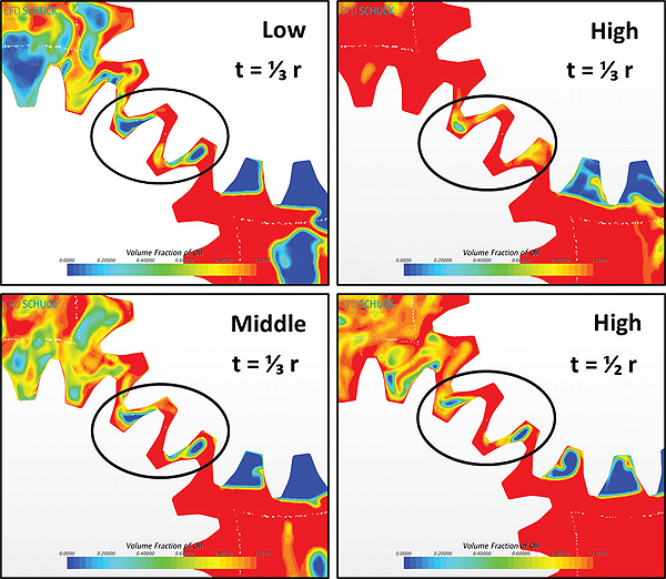
FIGURE 4: Volume fraction of oil between the intermeshing gears and for the three different oil-filling levels at 1⁄3 r (additionally for filling level high at 1⁄2 r).
On the other hand, the increase/decrease of the VF curves was not proportional between the different filling levels, and the middle filling level resulted in good values when compared to the highest level for gear 1. The comparison described above also indicated that the middle level resulted in small oil splashing effects compared to the available oil amount in the system. Pressure, torque and friction conditions were also comparably low for this filling depth.

FIGURE 5: a) Volume fraction of oil in the gearbox and b) on gear flanks after 1/3 r and 1 r.
The effect of including a linear ramp of the rotational frequency in the simulations was also studied and showed only a small influence on the oil fraction on the gear flanks.
Transient flow fields, pressures and torques in the gearbox and in the intermeshing gear region have been efficiently and effectively studied using the CFD method. The applied method offered a convenient way to study the influence of different oil-filling heights on the oil flow in the gearbox and on the volume fraction of oil on gear flanks.
Due to their high specific heat capacity, liquid lubricants also fulfill important functions concerning the cooling system of a gearbox. Future work will include oil temperature simulation and heat dissipation in the gearbox as well as heat conduction at the gearbox wall and at the gear flanks. These results served as a case study and experimental data will be essential for further model validation.
CFD Schuck Ingenieurgesellschaft mbH
www.cfd-schuck.de/en
Images courtesy of: CFD Schuck Ingenieurgesellschaft mbH, www.cfd-schuck.de/en
Filed Under: Software • FEA, Gears • gearheads • speed reducers, Motors (gearmotors)


Tell Us What You Think!