With motion control applications, a PID or proportional + integral + derivative controller is often implemented using tuning or by a trial-and-error process on the shop floor. But modeling of the motion control system allows analytical derivation of the PID controller terms.
By Tom Radigan | Advanced Motion Concepts Inc.
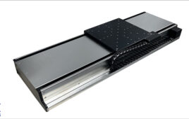
Modeling a motion control system begins with a block diagram. Diagrams show this model includes several different elements. Those of a closed-loop motion control system include an output position C(s) that’s constantly monitored using feedback … in this case, a linear encoder.
At the summing junction, feedback is subtracted from the target position R(s) and the result is an error E(s) that is sent to the PID controller. In motion-control applications the PID controller operates in discrete time with a sampling period. Every sampling period, the digital controller takes the error signal and produces an output within ±10 volts. It does this using a zero-order hold and a DAC or digital to analog converter. The zero-order hold refers to the process of sampling the signal and then holding between intervals; this introduces a delay into the system.
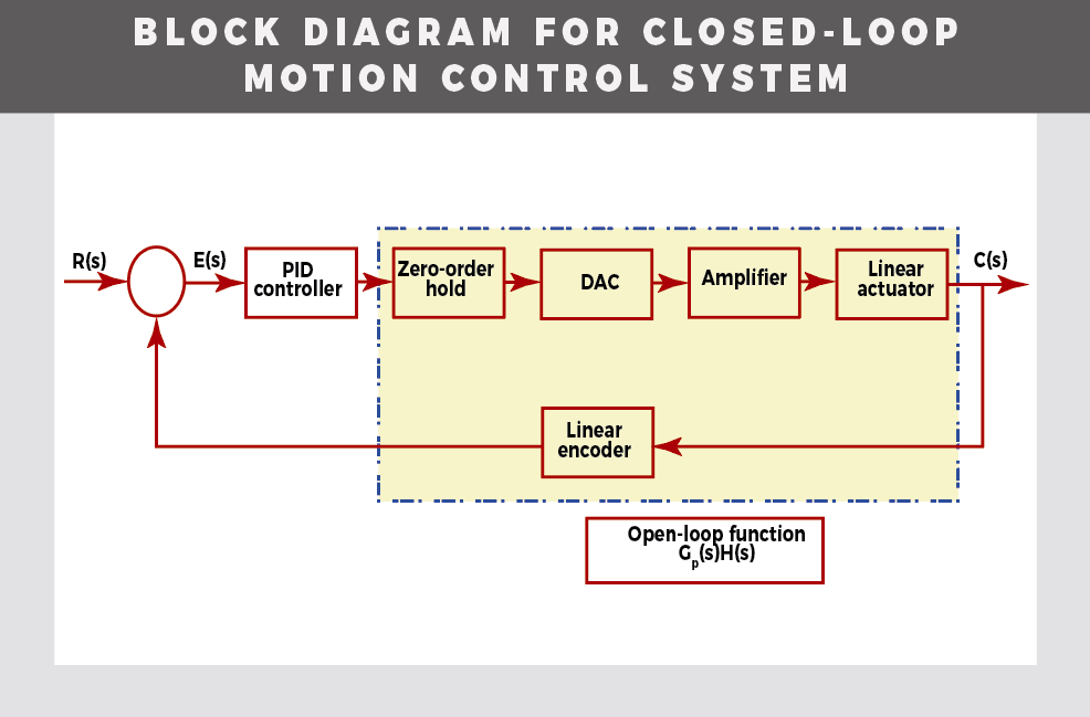
Here’s a closed-loop motion control system with an output position C(s) that’s constantly monitored using feedback … in this case, a linear encoder.
The digital to analog converter then takes the output of the PID controller and converts it to an analog voltage. The amplifier takes the voltage signal and produces an output current to the motor. The linear actuator takes the output current and produces a linear force which translates into output position. The linear encoder provides position feedback to the controller typically using a quadrature signal measured in counts. While the model is a mixture of discrete and continuous time elements, let’s execute an analysis in continuous time to simplify the model.
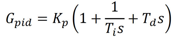
In fact, the modeling of the motion control system takes place in the s domain using Laplace transforms to derive the transfer functions. The s-domain transfer function for the PID controller in ideal form is:
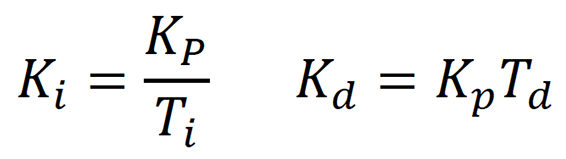
Where Kp is the proportional gain, Ti is the integral time constant, and Td is the derivative time constant. Letting Ki be the integral gain and Kd the derivative gain:
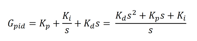
With these terms, the parallel form of the PID controller can be implemented:
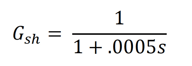
The zero-order hold transfer function is a first-order low-pass filter with sampling period τsh/2:
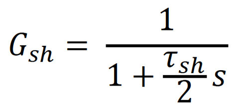
Letting τsh = 0.001 sec:
The DAC is modeled as a constant gain with n bit resolution:
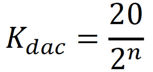
Letting n= 14 bit:
![]()
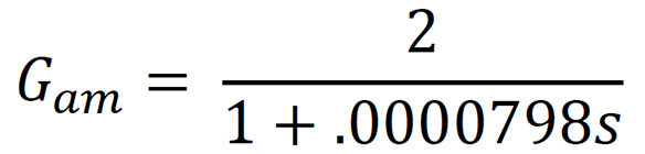
The amplifier is modeled as a constant gain Kam. To account for its limited bandwidth fb a first-order low-pass filter is added. The time constant of the filter is τam:
![]()
Letting Kam = 2 amps/volt and fb = 2,000 Hz:
The linear actuator is modeled as a gain Kf — the linear motor force constant plus the Laplace transform of F = ma. Here, a is the acceleration and m is the mass of the actuator and payload. The model assumes no friction as the system will be using an air bearing. The actuator transfer function with output in position (meters) and input in current (amps):
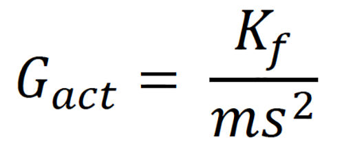
Letting Kf = 8.9 Newton/Amp and m = 00.5 kg:
![]()
The linear encoder is modeled as a gain Ke. If the resolution of the linear encoder is 0.1µm/count, then the linear-encoder gain is Ke = 10,000,000 counts per meter.
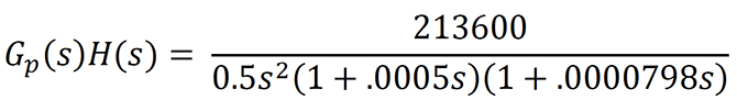
The multiplication of all elements from the zero-order hold to the linear encoder is known as the open-loop function — Gp(s)H(s). The open-loop function in this frequency domain analysis is:
The response of the open-loop function to a sinusoidal input is called its frequency response. The frequency response can be calculated by substituting s by jω in the open-loop function. Steady state response is then:

Where the difference between the output and input sine waves can be described by two parameters — magnitude M and phase φ. Magnitude measures the amplitude ratio and phase measures the phase shift. The magnitude and phase can be determined with a calculator for low-order systems. For higher-order systems, the magnitude and phase can be determined using technical computing software such as Matlab or GNU Octave.
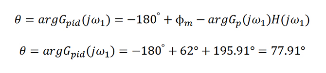
First — we need to calculate the phase of Gp(jω1)H(jω1) or argGp(jω1)H(jω1). This is the addition of the phase shift for each element of the open-loop function at the specified frequency ω1. The specified frequency must be chosen … let us choose 487 radians/sec:

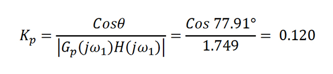
Second — the magnitude |Gp(jω1)H(jω1)| is calculated as 1.749.
Third — we need to specify the phase margin φm (or stability) of the system. Phase margin is the difference between the actual phase and -180° at the frequency ω1 where gain equals 0 dB. We choose a 62° phase margin.
Fourth — the argument or phase shift contribution of the PID controller can then be found:
The magnitude of θ must be less than 90° … Now we can solve for the PID proportional gain:
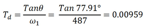
Solving for the derivative time constant:
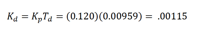
Solving for the PID derivative gain:
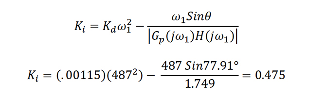
 Lastly, solving for the PID integral gain:
Note that these calculations are not a guarantee of system stability. The engineer must check the system response to a step input using the closed-loop transfer function … and must also check system stability using a Nyquist plot. Finally, to match the PID gains to controller, the form of the PID must be the same. For example, the motion controller PID must take the suitable or parallel form. Otherwise the gains won’t calculate to appropriate values. For more information, read Feedback Control Systems, Fifth Edition — by Charles L. Phillips and John M. Parr.
How are PID parameters configured for variable frequency drives?
Effects of PID and machine parameters on positioning-system performance
FAQ: What are PID gains and feed-forward gains?
Filed Under: Encoders • linear, Linear Motion Tips

Tell Us What You Think!