Profiled linear guides are typically used in conjunction with a drive system, such as a belt or ball screw, to provide rigid, accurate motion. When the specification calls for extremely long travel and high thrust force, the drive mechanism of choice is commonly a rack & pinion system. Fortunately for design engineers and machine builders, several linear guide manufacturers offer profiled rail guides with integrated rack & pinion assemblies. Integrating the drive and guide functions into one mechanism gives several advantages, not the least of which is ease of assembly. But integrated profiled rail rack & pinion systems offer other benefits as well.
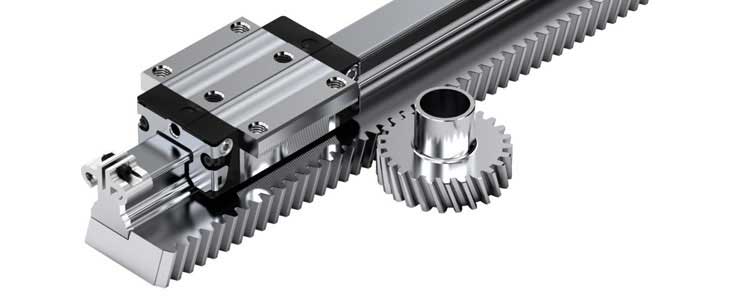
Gear racks from Bosch Rexroth are designed to accommodate series SNS guide rails, in sizes 25, 30, and 35.
Image credit: Bosch Rexroth Corporation
Design and benefits
Linear guides incorporate gear racks in one of two ways: with the gear teeth machined directly onto the profiled rail, or with a gear rack designed to allow mounting of the rail directly on the rack. While the integrated design is more compact and provides the easiest assembly, the benefit of having the gear rack and profiled rail provided separately is that the components can be replaced independently if one is damaged. This lowers repair time and cost and simplifies replacement part stocking.
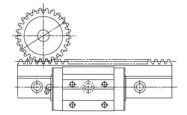
The THK GSR-R assembly is a profiled rail with a gear rack machined directly onto the rail structure, resulting in an extremely compact package.
Image credit: THK Co., Ltd.
The majority of profiled rail rack & pinion assemblies use helical teeth, which operate with less noise and have a higher load capacity. Some manufacturers do, however, offer straight cut gears, which require less lubrication and are simpler to install. Regardless of tooth design, virtually all profiled rail rack & pinion assemblies are manufactured with a pressure angle of 20 degrees. The pressure angle, as explained by gear manufacturer Boston Gear, is “the angle at a pitch point between the line of pressure which is normal to the tooth surface, and the plane tangent to the pitch surface.” The pressure angle is significant because it influences the load carrying capacity, noise, and backlash behavior of the gear. The 20 degree pressure angle is chosen for its high load capacity.
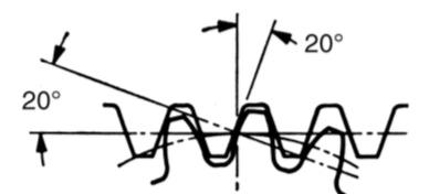
Integrated profiled rail rack & pinion assemblies are typically designed with a 20 degree pressure angle.
Image credit: Boston Gear
Sizing and selection considerations
Like other drive units, a key element of sizing a rack & pinion system is to check that the transmitted torque doesn’t exceed the maximum allowable torque, which is based on the pinion design, rack hardness and strength, and tooth pitch. Also important to consider is the pitch deviation, which affects positioning accuracy.
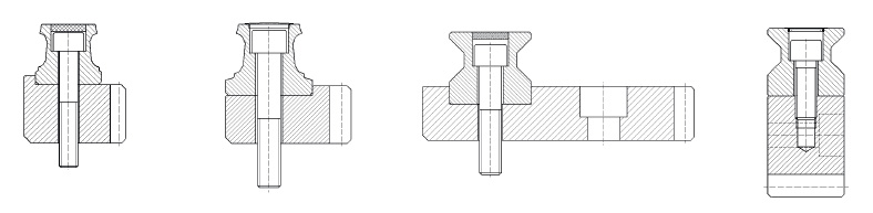
Schneeberger offers custom gear racks for mounting linear guides in a variety of configurations. They also offer both straight and helical gear teeth.
Image credit: Schneeberger AG
In addition to a compact design and simple assembly, another significant benefit of integrated profiled rail rack & pinion devices is the ability to achieve virtually unlimited travel lengths. Both profiled rails and gear racks can have multiple sections that are precision-joined, so joining lengths of integrated rail and rack is an effective and relatively simple way to achieve long travel lengths. In addition, multiple pinion gears can be used on the same rack, to provide independent movement of several workpieces, robots, or tools.
Rack & pinions are known for their ability to withstand moderate debris and liquids, but their open design does make them susceptible to contamination, so mounting orientation (i.e. mounting the assembly on its side or upside down) should be considered for extremely harsh environments. And, in many applications, the assembly can be mounted above the working area, which limits exposure to debris and liquids.
The most common applications for integrated profiled rail and gear racks involve material handling or transport over long lengths. One example is positioning multiple welding robots independently along an automotive assembly line. Other examples include packaging equipment and machining centers with extremely long strokes.
Feature image credit: Schneeberger AG
Filed Under: Linear Motion Tips, Motion control • motor controls


