The most appropriate type of low-power dc motor that can be selected for any application depends on several factors. First, determine the correct gearhead ratio when one is used; second, determine the maximum mechanical power that the motor must produce; third, decide on the type of bearings that are most compatible; and last, select an appropriate position sensor when required.

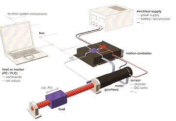
Motor drive architecture can be as simple as a dc motor, a battery, and a power switch or as complex as the one shown here. Required load movement, speed, accuracy, and a host of other conditions dictate which components should be used.
When a gearhead will be part of the system, it must be selected first. This is because the motor must match the grearhead’s input speed and torque to ensure that the load is driven correctly. Next, select the type of dc motor needed for it, and consider the following parameters and options: speed, torque, direction of rotation, motor dimensions, commutation system, type of bearings, and shaft design. After selecting the motor, then determine whether you will need an encoder, controller, and a brake.
After you determine the system architecture, select a motor with sufficient speed and torque. The motor shaft speed cannot exceed the maximum rating of the motor, that is:
Smax = Smot
Where:
Smax = maximum allowable motor speed rating, rpm
Smot = motor speed, rpm
Next, determine the rated continuous motor torque. It should be sufficiently greater than the effective torque that the motor must generate:
TC = Tmot
Where:
TC = continuous rated torque of the motor, ft-lb
Tmot = required effective torque, ft-lb
Calculate the maximum rated continuous torque based on the maximum rated continuous current of the motor, which in turn, is limited by the maximum allowable winding temperature. Torque and winding current ratings are usually given at 25o C ambient temperature without a heat sink being used. Some motor manufacturers also include torque ratings with a heat sink.
It should be stressed that the rated continuous torque depends on the ambient temperature and on the installation. When the motor is intended for elevated temperature operation, the rated torque must decrease, but when the motor can be bolted to a metal frame (which serves as a heat sink), the rated torque may increase.
During startup, the motor should be able to generate the maximum torque, called the stall torque, or zero-speed torque. Larger motors can usually produce a torque four times higher than the continuous torque rating for short periods without damage.
Also, motor service life and several other factors should be considered when selecting the commutation system. These factors are different for mechanical (brush type) as compared to electronic (brushless type) commutation systems: both have advantages and weaknesses.
Brushed dc motors
In conventional brushed dc motors, the stator has permanent field magnets and the rotor contains armature windings. Field magnets create stationary magnetic fields, and rotor windings form electromagnets, which are terminated at the commutator segments. As the rotor turns, brushes slide from one pair of commutator segments to the next and apply power to the winding that needs to interact at that moment with the stationary magnetic field to sustain rotation. The brushed commutation system is simple and requires only dc voltage for the motor to run. This type of motor can be connected directly to a battery, which makes it ideal for battery-powered tools. It is exceptionally efficient and relatively inexpensive.
Unfortunately, the major drawbacks of a brush-type motor include limited service life (typically 1,000 to 5,000 hours) and limited speed (typically below 10,000 rpm), which are usually dictated by the commutation system. That is, brushes and commutators require periodic maintenance and often are the primary source of motor failures.

Although brushed dc motors can be driven above their maximum allowable speed, this usually significantly reduces motor service life. As the motor speed increases, the commutator and brushes wear out faster. Two factors are responsible. As the speed increases, so does the friction between the brushes and the commutator, which makes the brushes bounce. The bounce interrupts current and generates arcs that tend to erode both the commutator and brushes. The second factor is the higher induction voltage generated by the higher speed, which also generates more arcing and erosion.
To help alleviate the wear problem, some manufacturers offer small motors with precious metal brushes and silver alloy commutators. Larger motors, motors with reverse direction, and motors operating in a frequent start-stop mode normally have graphite bushes with copper alloy commutators. Precious metal and graphite brush/commutator systems differ in cost and maintenance, and are typically used in different types of applications.
Brushless motors
The rotor of a brushless motor has no windings. Instead, it contains permanent magnets. The windings are stationary and the current is constantly varied by the electronic controller. The interaction of the fields created by the permanent magnets of the rotor and the stationary electromagnets of the stator produce a force that sustains the rotation.
Because the stator current varies in proportion to the rotor’s angular position, the controller must sense the spatial relationship between the two at all times. Some controllers require a special Hall-Effect sensor or a rotary encoder to detect rotor position while others do not: they automatically and internally sense back-emf, which essentially accomplishes the same thing.
The two types of commutation systems used with brushless dc motors include what are called block commutation and sinusoidal commutation. The two methods differ in cost, amount of torque ripple, and are suitable for different applications.
When a block-commutation controller is used, the current in each winding is continuously stepped through three states: positive, zero, and negative polarity. The phase shift between the windings depends on the number of rotor pole pairs. One of the drawbacks of block commutation is rather high torque ripple.
Without a feedback sensor, a block-commutation system should not be used below 1,000 rpm or in highly dynamic servo systems. The cost of such a system is relatively low, but the applications are limited to electric drills, screwdrivers, grinders, fans, pumps, and some milling machines. Adding a feedback sensor increases the overall system cost, but it makes the system suitable for servo drives. When an encoder is installed at the load, it can be used for positioning systems.
By comparison, sinusoidal commutation systems require a Hall Effect feedback sensor or an encoder. The current in each phase increases and decreases in extremely small increments (to 2000 steps per revolution), and closely approximates a sine wave. Such a system exhibits virtually no torque ripple and the motor runs especially smooth even at low speeds. This system is suitable for precision positioning and servo-drive applications.
The service life and maximum speed of brushless motors are typically limited only by the bearings: a life of 20,000 hours and a maximum speed of 50,000 rpm are common. The disadvantages include the need for an electronic commutation system and the slightly lower efficiency caused by rise of the eddy current losses at higher speeds.
Bearings
Sintered sleeve bearings and ball bearings are the most common types, and differ in several critical properties. Sintered bearings are more economical and are typically used in smaller dc motors. Suitable only for continuous operation with low bearing loads; this type of bearing should not be used below -20oC, in a vacuum, or with rotating loads.
Ball bearings are more expensive, but can be used for most operations: low speed, high speed (typically up to 10,000 rpm), continuous, reversing, and start-stop. This type is well suited for high axial and radial loads; it allows smooth operation with long service life. Standard lubrication is acceptable from -20 to +100oC. Special types of lubrication should be used for extremely high or low temperature operation.
Winding options
Most dc motors have several winding options available for each basic motor model. The winding is selected to align the electrical and mechanical parameters of the motor within the limitations of the available power supply voltage and current.
When the motor voltage is constant, the shaft speed decreases linearly as the load increases. Higher loads require higher torque and hence higher current. The only way to maintain speed of a dc motor as the load changes is to vary the voltage. The speed vs. torque line shown in the curve illustrates the relationship between the motor speed, torque, current, and voltage.
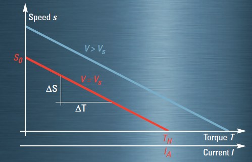
When the load increases, so does the required torque and winding current. If the motor voltage is constant, for example V = VN, the speed decreases in a linear fashion. Increasing the voltage will increase the speed, but the slope remains constant for a given motor.
Motor specifications indicate the nominal voltage, VN, which is a reference value, and not the voltage required to run the motor. Since many motor specifications depend on voltage, they are listed at the nominal voltage, so an accurate comparison of specifications can be made. However, the speed vs. torque line should always be considered.
When selecting the winding, first find all the speed-torque points required during every mode of load operation. Especially critical are the extreme points at the end of acceleration when the torque and speed are at their peak values.
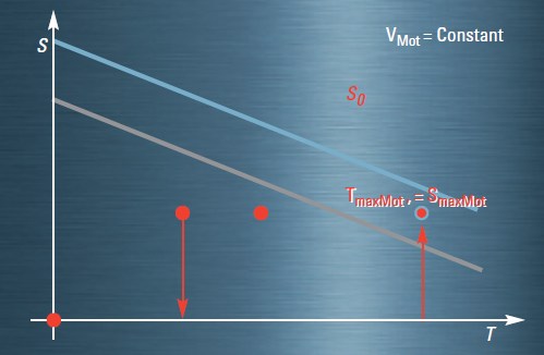
VMot is the maximum voltage available from the power supply or battery. Three working points cover all operating conditions. The blue line is the speed vs. torque line of a correctly selected motor and winding. A motor with the gray speed vs. torque line will not have sufficient torque when the maximum speed and torque are needed.
Highlight the maximum voltage available from the battery, power supply, or controller. Then select the winding that has its speed-torque line located above all normal operating points.
To confirm that the current available for the winding can generate sufficient torque for continuous operation and for short-time overloads, use the following simplified equation:
Imot > Tmax/kM + Io
Where:
Imot = maximum power supply current available to power the motor, A
Io = no-load current (losses), A
Tmax = maximum required torque, ft-lb
kM = motor speed constant
After selecting the motor, verify that the controller and feedback sensors still satisfy the specifications. Also, make certain that the drive is fully compatible with the overall system
constraints. For example, consider available space, weight, atmosphere, vibration, noise, electromagnetic compatibility, CE, RoHS, and other special requirements.
Information for this article was provided in part by Maxon Motor Ag, Maxon Academy, and handbook, “The Selection of High-Precision Microdrives.”
Maxon Motor, AG
www.maxonmotor.com
Filed Under: Bearings, Motion control • motor controls, Motors • dc

Tell Us What You Think!