Design World

  • Home
  • Technologies
    • 3D CAD
    • Electronics • electrical
    • Fastening & Joining
    • Factory automation
    • Linear Motion
    • Motion Control
    • Test & Measurement
    • Sensors
    • Fluid power
  • Learn
    • Ebooks / Tech Tips
    • Engineering Week
    • Future of Design Engineering
    • MC² Motion Control Classrooms
    • Podcasts
    • Videos
    • Webinars
  • LEAP AWARDS
  • Leadership
    • 2022 Voting
    • 2021 Winners
  • Design Guide Library
  • Resources
    • 3D Cad Models
      • PARTsolutions
      • TraceParts
    • Digital Issues
      • Design World
      • EE World
    • Women in Engineering
  • Supplier Listings

Swage Mount PCB Pins Provide Connectivity For Interconnect Applications

By Mill-Max Mfg. Corp. | August 24, 2017

Share

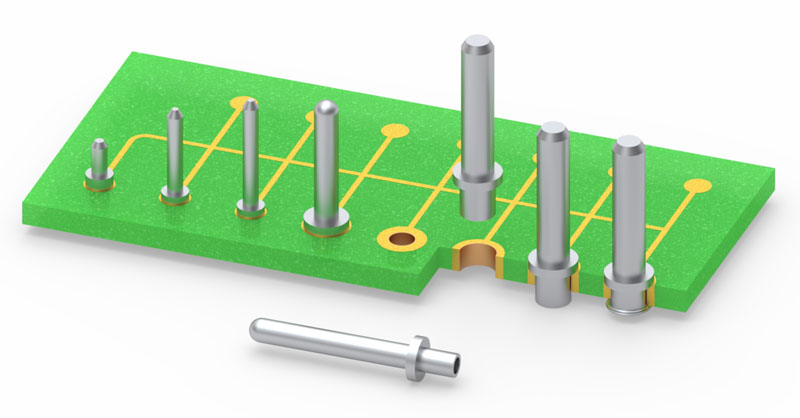
Mill-Max has added to its diverse mix of swage mount PCB pins with six new offerings designed for interconnect applications. These swage mount terminals are designed to be mechanically fastened to a board or panel and plugged into sockets or soldered into mating boards in board stacking and other interconnect configurations.

Swage pins are often thought of as wire-to-board soldering terminals and test points or as hardware such as PCB standoffs, but they are also an excellent choice for board-to-board interconnects. They are cost effective due to their simple design, don’t require the more precise PCB hole specifications associated with most press-fit pins and can be processed in volume with semi-automatic or automatic equipment. Swage assembly is a method of mechanically fastening pin terminals to a circuit board, similar in style to riveting. After the pins are swaged, they are soldered, providing a robust mechanical and reliable electrical connection.

The swage pins featured here are offered in various diameters and lengths to suit a wide variety of interconnect applications. They are useful when space is limited, near the edge of a board for example, where a connector with its housing is not an option. The swaged pin takes up relatively little space and is secure without the need of an insulator. The longer pins are perfect for overcoming the height of taller board components (large capacitors, transformers, power supplies, potentiometers) to connect to a daughter card or other module, while the low profile 4658-0 may be used on boards which are primarily SMT, to keep the overall stacked board assembly height to a minimum .

All the pins are high speed precision turned from brass alloys and annealed to prevent cracking during the swaging operation. The standard plating for these pins is matte tin over nickel with other plating options available upon request.


Filed Under: Capacitors, M2M (machine to machine)


Related Articles Read More >

Part 6: IDE and other software for connectivity and IoT design work
Part 4: Edge computing and gateways proliferate for industrial machinery
Part 3: Trends in Ethernet, PoE, IO-Link, HIPERFACE, and single-cable solutions
Machine Learning for Sensors

DESIGN GUIDE LIBRARY

“motion

Enews Sign Up

Motion Control Classroom

Design World Digital Edition

cover

Browse the most current issue of Design World and back issues in an easy to use high quality format. Clip, share and download with the leading design engineering magazine today.

EDABoard the Forum for Electronics

Top global problem solving EE forum covering Microcontrollers, DSP, Networking, Analog and Digital Design, RF, Power Electronics, PCB Routing and much more

EDABoard: Forum for electronics

Sponsored Content

  • Renishaw next-generation FORTiS™ enclosed linear encoders offer enhanced metrology and reliability for machine tools
  • WAGO’s smartDESIGNER Online Provides Seamless Progression for Projects
  • Epoxy Certified for UL 1203 Standard
  • The Importance of Industrial Cable Resistance to Chemicals and Oils
  • Optimize, streamline and increase production capacity with pallet-handling conveyor systems
  • Global supply needs drive increased manufacturing footprint development

Design World Podcasts

June 12, 2022
How to avoid over engineering a part
See More >
Engineering Exchange

The Engineering Exchange is a global educational networking community for engineers.

Connect, share, and learn today »

Design World
  • Advertising
  • About us
  • Contact
  • Manage your Design World Subscription
  • Subscribe
  • Design World Digital Network
  • Engineering White Papers
  • LEAP AWARDS

Copyright © 2022 WTWH Media LLC. All Rights Reserved. The material on this site may not be reproduced, distributed, transmitted, cached or otherwise used, except with the prior written permission of WTWH Media
Privacy Policy | Advertising | About Us

Search Design World

  • Home
  • Technologies
    • 3D CAD
    • Electronics • electrical
    • Fastening & Joining
    • Factory automation
    • Linear Motion
    • Motion Control
    • Test & Measurement
    • Sensors
    • Fluid power
  • Learn
    • Ebooks / Tech Tips
    • Engineering Week
    • Future of Design Engineering
    • MC² Motion Control Classrooms
    • Podcasts
    • Videos
    • Webinars
  • LEAP AWARDS
  • Leadership
    • 2022 Voting
    • 2021 Winners
  • Design Guide Library
  • Resources
    • 3D Cad Models
      • PARTsolutions
      • TraceParts
    • Digital Issues
      • Design World
      • EE World
    • Women in Engineering
  • Supplier Listings