After more than 40 years of use in thousands of applications ranging from the saw mill to the clean room, and from light to heavy loads, guide wheels have proven features that meet performance, durability, and cost requirements in a variety of demanding conditions.
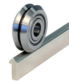
Linear guide systems are chosen for an application based partly on their precision and speed, but also on a host of other operating conditions such as environment, length, duty cycle, and temperature, to name a few. One type of linear motion system that should not be overlooked is guide wheel systems; in many applications and environments they have significant advantages.
Guide wheels operate in a variety of environments. Most notable for their ability to outperform re-circulating ball technology in harsh environments due to their contained ball circuits, they also have other less known advantages. Applications with noise level requirements can benefit from decibel level reductions by as much as 20% compared to other re-circulating ball technologies. This can be a critical design advantage in medical equipment such as magnetic resonance imaging and scanning equipment.
The guide wheels’ smooth motion is a result of several features: a constant radius ball bearing path; the use of carbon, stainless steel, and composite components; and the antifriction double-row angular-contact bearings. The steel versions permit fast acceleration (up to 5 gs) and high speeds (up to 5.5 m/s), while composite polymer versions provide an economical choice for low noise, smooth motion, chemical environments, and light load applications.
Critical and extreme environments
In each of the three major linear motion technologies (profile rails, round rails, and guide wheels), ball bearings recirculate. In profile and round rails, however, the bearings ride on the guide rail and are exposed to any of the contaminants that may settle on the rail. The bearings in a 90° double-vee guide wheel are self-contained and isolated from the environment, so there is no contact between the bearings and the rail. Additionally, most contaminants that settle on vee guide rails are swept away when the wheel passes over the rail. When the wheel spins at a constant speed, the diameter at the inner vee travels at a slower rate than the diameter at the outer vee, causing a velocity gradient that pushes the debris outward.
The double-vee design was originally developed in 1967 as a replacement for flat rollers on machinery at a fertilizer packaging plant, where debris from the processing operations continuously clogged the bearings, causing equipment to shut down. The 90° double-vee approach, with its inherent wiping action, proved ideal.
Wheel configurations are also available with special materials that are suitable for clean room, wash down, and high temperature environments up to 500°F. Other areas where guide wheels excel include:
• Food, beverage, and pharmaceutical packaging and processing
• Pick-and-place applications
• Security/defense
• Machine tools
• Printing
• Welding/pipe applications
Guide wheel systems also accommodate long travel lengths at a low installed cost. Single-piece track lengths are available up to 20 ft (hardened) and 22 ft (unhardened). Sections can be butt-jointed to create driven or un-driven systems of virtually unlimited lengths. Systems up to 80 ft are not at all uncommon.
Tolerances
Guide wheel track does not require grinding and finishing operations to achieve tight tolerances. Generally, an-off-the-shelf guide wheel system should be able to meet positioning tolerances of +/- 0.005 in. depending on the track-mounting surface. With track made of drawn steel, which is hardened and ground to specified tolerances, a guide wheel system should be able to meet positioning tolerances of +/- 0.001 in.
Most designs using vee wheels rely on the base mounting surface of the track to maintain tolerances and accuracies. The track will conform to the straightness, flatness, twist, and parallelism of the prepared mounting, provided it is more rigid than the track itself, and should be designed as such. Designs requiring less accuracy will require less demanding mounting surfaces and therefore will be less costly.
For example, if +/-0.004 in. tolerances are required, a guide wheel system can be bolted to a semi uneven surface and a carriage will function properly, providing smooth movement. Surface preparation is minimal and installation time and costs are low. However, for systems requiring +/-0.001 in., better mounting surface preparation will be required.
Lubrication
As with many bearing systems, proper lubrication will enhance service and product life.
When lubrication is not possible in an application, guide wheels are often the preferred choice. For some medical applications, for example, guide wheels are specified to run dry to eliminate the possibility of contamination.

One of the advantages of guide wheels, especially 90° double-vee versions, is their ability to function even in harsh environments. Contaminants that settle on vee guide rails are swept away when the wheel passes over the rail. The diameter at the inner vee travels at a slower rate than the diameter at the outer vee, causing a velocity gradient that pushes the debris outward.
Sizing tips
Guide wheels come in different diameters to accommodate varying load requirements. For example, a single 75 mm size 4XXL double-vee wheel can handle radial loads of 3,215 lbf. A single 150 mm vee bearing wheel has a radial load capacity up to 50 kN (11,240 lbf) while a four-wheel carriage is capable of double that.
Load evaluation can be fairly tricky with guide wheels, so it is important to clearly understand the conditions under which they will be used. Start with determining whether the loads are radial or axial.
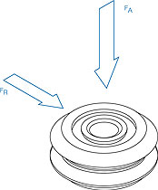
The conditions under which a guide wheel will function are important. You must determine whether the loads will be radial (FR) or (FA)axial.
FR: Radial load refers to the load applied in a direction perpendicular to the axis of rotation.
FA: Axial load refers to the load applied in a direction parallel to the axis of rotation.
Several factors influence the service life of guide wheel systems. The following simple method estimates the load/life relationship by defining the loading conditions. The process accounts for the size of the bearing elements, relative spacing; and the orientation, location and magnitude of the load. The equations are based on clean and well-lubricated track conditions. The ratings and calculations are theoretical values based on ideal conditions. Most applications will involve less than fully optimum conditions, and in a situation where a particular size bearing may appear marginal in capacity, selection of the next larger bearing size is recommended.
Calculating load/life requires a basic understanding of the principles of statics, the ability to work with free-body diagrams, and the capacity to resolve externally applied forces on a carriage assembly into the radial and axial reaction forces at each guide wheel. The life of a guide wheel system is limited to the life of the most heavily loaded bearing in the design.
There are three steps for sizing and selecting a guide wheel assembly, including determining radial and axial loads, calculating the load factor for the most heavily loaded wheel and applying such factors to compensate for speed, vibration, shock and environment.
Step One: Calculate the radial (FR) and axial (FA) loads on each bearing element in the guide wheel system design. All standard considerations involved in statics calculations must be considered, including inertial forces, gravitational forces and such external forces as tool pressure, bearing element spacing, and magnitude and direction of the payload. Any external forces that generate a reaction through the wheel-track interface must be considered:
Step Two: Calculate the load factor for the most heavily loaded bearing. (See catalogs for maximum load capacities)
LF = FA / FA(max) + FR / FR(max)
Where:
LF = Load Factor
FA = Resultant axial load on guide wheel
FA(max) = Maximum axial working load capacity of guide wheel
FR = Resultant radial load on guide wheel
FR(max) = Maximum radial working load capacity of guide wheel
Bearings should be sized such that LF < 1.
Step Three: Apply an adjustment factor to the equation to determine system life expectancy.
Because of such varying application requirements as load, speed, shock, vibration, contamination and duty cycle, a safety factor must be applied to the maximum axial (FA(max)) and
radial (FR(max)) working load capacities.


Life = (LC / (LF)3)AF
Where:
LF = Load Factor
LC = Life Constant
AF = Adjustment Factor
Compared to other linear motion systems in certain applications, guide wheels are faster to assemble, easier to maintain, and are very cost efficient.
Bishop-Wisecarver Corporation
www.bwc.com
Other linear motion technologies
In an environment relatively free of debris, Teflon bushings offer excellent performance at high speeds with low noise. Teflon bushings should not be used in clean room applications, however, because the bushings tend to generate particulates.
Round rail technology is a reasonably priced option for less demanding applications. However, they can be inadequate for dirty environments, low noise or high-speed requirements.
Square rails provide excellent rigidity and are also a good choice for pinpoint accuracy requirements and “extreme” loads. The square rail is often specified for heavy loads, but unless the application also calls for extreme precision, which requires a significant amount of surface preparation, it may not be the most cost effective choice.
Guide wheels can handle axial or radial loading. Profile rails, on the other hand, will take both radial and axial forces, but are de-rated 50% axial when pulling versus pushing force.
Filed Under: LINEAR MOTION, Motion control • motor controls


Tell Us What You Think!