 When intermittent power density is of a required high value, using classic RMS calculations and speed-torque performance curves as the sole selection methods may be problematic. That’s because such an approach might cause motor or drive undersizing.
By Hurley Gill • Senior applications and systems engineer | Kollmorgen
Using classic performance curves with RMS calculations is perfectly acceptable for most servo applications. However, if an application’s intermittent torque is large relative to its motor’s continuous capability for some relative time period, the thermal time constants of the proposed setup need consideration. Tight or enclosed design spaces can exacerbate thermal issues.
This article presents visuals for understanding how significant dynamic effects are on servo motor thermal time constants — especially when the application requires an I_actual > I_continuous for an extended time.
Servo motors generate heat due to internal losses, and each motor’s distinct ability to dissipate its internally generated heat determines its rated continuous capacity … more after the jump.

Clearly, there are many factors to address during the machine design planning phase. Servo motor and drive selection for a given application affects the mechanism’s chance of success for getting target performance for all conditions — normal operation, E-stops, and foreseen potential events. Where a motor’s capability of torque and current, is needed above continuous capability to reach specific goals for an extended period of time; using a simplified graphical approach (Figure B later in this article) can help overcome initial design challenges for broad risk management decisions.
Conventional servo motor applications see various velocity demands, with torque requirements that enter and exit the intermittent capability over the defined motion profile. Traditionally, peak currents exceeding a servo motor’s continuous capability help the motor meet acceleration and deceleration requirements. Motion profiles most often need these peak currents for short periods of time (often in the millisecond range) not exceeding the typical maximum of 4 to 5 seconds available from a drive amplifier.
In these routine cases of intermittent-duty operation, it’s usually unnecessary to select a motor with a continuous-duty capability that satisfies the application’s peak-torque requirement. Instead we simply:
- Use a root mean square (RMS) equation to find the application’s effective continuous torque (Trms) and velocity (Nrms) requirement and then …
- Ensure that this equivalent operating requirement falls within the continuous (and thus thermal) capability of the chosen motor chosen …
- While verifying that the required peak Torque (Tpk_required) is less than available peak torque (Tpk_available) from the selected motor and drive, at its needed rpm.
Special application conditions
The expansion of closed-loop motion control technology into less conventional applications often results in specific requirements or conditions of operation that exceed ordinary intermittent-duty operation. However, even conventional applications sometimes present special conditions.

For example, a design may specify that in the event of an emergency stop (E-stop) all controlled motion must halt before the removal of mains power and within a specific amount of time. For most applications, this isn’t usually an issue … but on large machines with significant kinetic energy, time needed to bring an axis’ motion to a stop can easily exceed the typical maximum 4-to-5 seconds of available peak current from a paired motor-drive combination [Ic(drive) equal to approximately Ic(motor)].
This requirement, though generally not demanding a larger motor, often requires a higher continuous current drive to ensure the needed peak current (Ipk_required) is available during an E-stop deceleration. For large machines, E-stops requirements in the 20 to 40-second time range are somewhat common.
Many of today’s pulse width modulation (PWM) drives are designed with foldback overload circuits or an algorithm using the thermal time constant of the copper coil (TCT_coil) — whether the current is folded back to the continuous current of the drive or motor. But to satisfy some of these atypical servo applications, the typically paired motor-drive combination that would otherwise be selected is unsatisfactory.
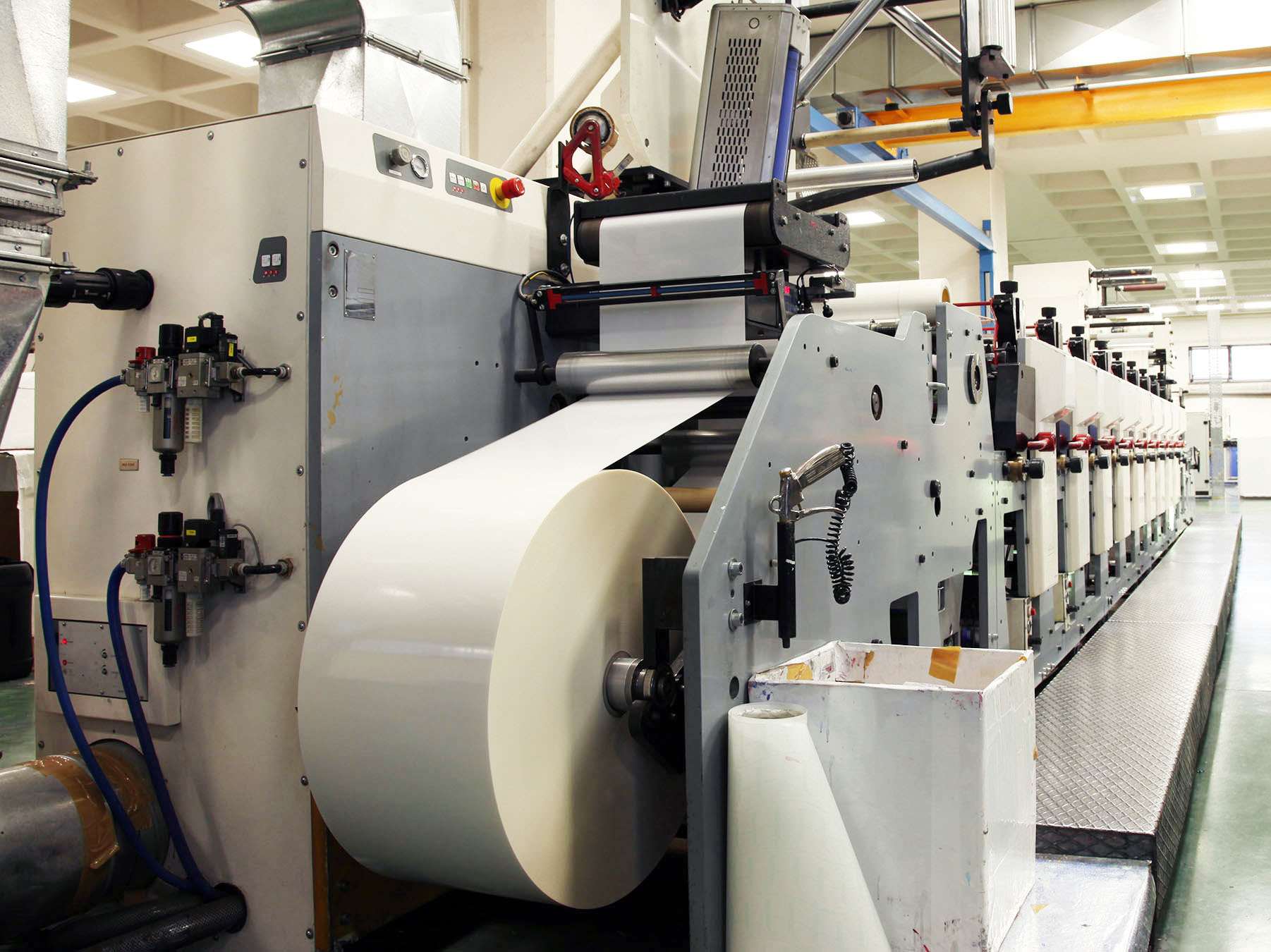
For some large machines (such as this one for printing) E-stops of 20_seconds to 40_seconds are often acceptable.
Many of today’s servo motor applications have operating conditions and potential events that need to be addressed during servo motor sizing and selection. Consider some other examples:
- There could be a vertical-axis requirement — necessitating a servo motor capable of holding a load greater than its continuous capability for a specific amount of time before engagement of a static brake. (That’s especially relevant as it’s typically undesirable to cycle a static holding brake through engagement and disengagement during normal production cycles.)
- There could be an axis requirement that necessitates a motion system that can handle undesired events in-which a load becomes stuck or otherwise hindered from movement. Here, the motor must be capable of surviving some peak current for the full duration of the commanded move (even when not properly functioning).
Whether it’s easy or impossible to replace a motor once it’s installed (in a normal environment, in space or underwater, or in an area exposed to radiation) it’s always best to select a servo motor-drive combination that minimizes the risk of failure due to atypical events or normal operating requirements — as these in turn maximize reliability and safety.
Overload and the effect of power losses
Depending on the complexity of requirements, many of these applications need torques (and thus currents) above the motor’s continuous capability (Ic or I_rated) at the application’s required rpm (e.g. Npk, Nrms). Hence, the potential limiting or control of the motor’s power losses must be considered so that the motor can execute the necessary work or specific event — while the motor’s insulation system is protected from thermal overload.
At this juncture, the motor’s demanded current (I_actual) is greater than the motor’s continuous rated current (Ic) capability for a significant enough period of time relative to the motor’s overall thermal time constant (TCT_motor), that the TCT_motor becomes dominated by the TCT_coil due to the relative heat transfer rates between the used non-homogeneous materials. For these specific cases or events under evaluation, the previously referenced RMS calculations over a given motion profile are usually invalid, though still calculated to ensure overall product selection requirements; because events needing overload situations can differ greatly from one application to the next.
To satisfy applications with potential events or conditions requiring a peak current (I_actual) to deliver a peak torque (Tpk) for a qualified period of time, we also need to determine if the motor’s winding/coil can sustain the overload current needed without sustaining motor-insulation damage.
Available life of a motor’s insulation (based on its continuous rating) is halved for every 10° C the motor experiences beyond its continuous rating.
We can estimate the time to rated ultimate temperature (t_ ultimate) of the motor’s coil/winding from a cold start (ambient) using:
t_ultimate = -TCT_coil(mounted) x ln[1-(W_loss(rated)/W_loss(actual))]
or
t_ult. = -TCT_winding x ln[1-(Ic2/I_actual2)]
where W_loss(rated) is substituted with: Ic2 or I_rated2
and W_loss(actual) with: I_actual2
Note that for these conditions, I_actual is greater than the motor’s Ic (continuous rated current of the servo motor at low or stall rpm). What’s more, under this condition, actual W_loss will continue to exceed rated values — potentially causing thermal runaway if there’s a delay in power removal.
Formula assumptions for motor heat
Of course, the above substitution (with the appropriate I2 for watts in both the numerator and denominator) assumes constant power dissipation with a constant applied [step input] current. That value — due to the actual winding temperature rise from ambient temperature (e.g. Rm(25° C)) to the target temperature based on W_loss(actual) — is incorrect. However, that value offers a conservative approach with Rm(hot) assumed constant, over solving a dynamic nonlinear differential equation. What’s more, even further manipulation of the formula is required for real-world application of the motor starting from a non-ambient temperature based on an Irms value.
However, whether the equation is manipulated or not, the preformed calculations tend to be done at only one or two points when needed. Unfortunately, that means that the substantial effect of actual current (I_actual) exceeding continuous capability (Ic) is often missed.
So in this article, we present a plot in Figure A to demonstrate the effects of demanded Watts_loss exceeding the design’s continuous capability. The plot also lets us graphically determine a relative (if not effective) TCT for a specific condition under evaluation. That in turn provides a way to overcome design challenges where the ratio: I_actual (under evaluation) / Ic (continuous current) is greater than one and known for the production of the application’s needed torque (T_required).
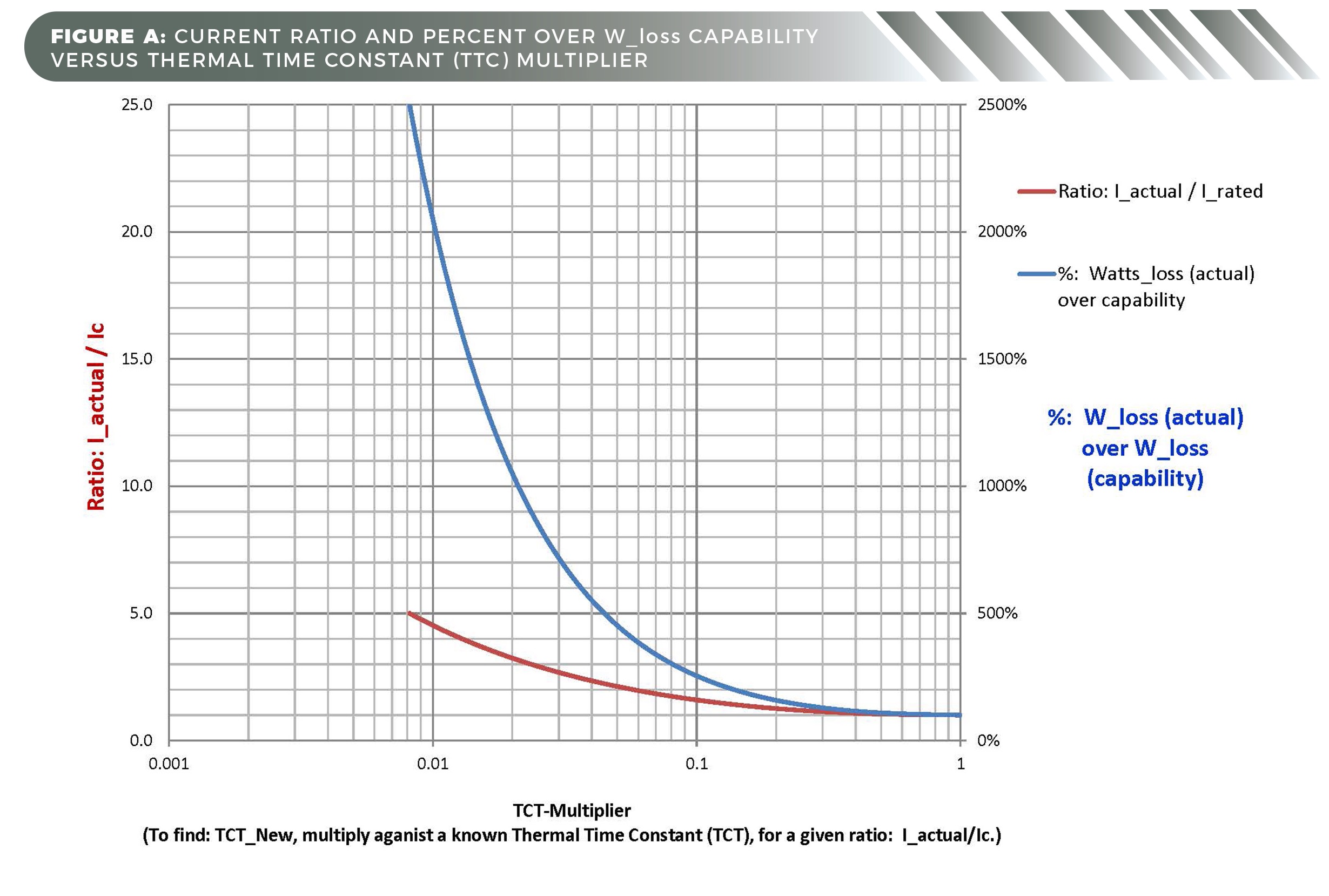
Figure A — Shown here is the thermal time constant (TCT) effects as I_actual is increased to beyond Ic. Click to enlarge.
This article also lets us compare effective TCT_motor and TCT_coil(air) under their specific condition using Figure B.
Most of today’s servo motors have excellent thermal conductivity between the motor windings, laminations, and frame — especially in motors with epoxy encapsulation. That said, these non-homogeneous materials still have vastly different heat-transfer capabilities.
However, under the subject condition, the thermal time constant of the motor’s mounted coil (TCT_coil(mounted)) is the dominant factor. In addition, the TCT_coil(air) is likely too conservative to be of reasonable use, as it’s calculated from the magnet wire’s specific mass without any consideration of it being mounted within the motor’s frame.
The TCT_coil(mounted) value (henceforth identified as the TCT_winding) represents the first level of materials contact of the thermally nonhomogeneous motor materials — more specifically, at the interfaces between the coil and epoxy and air and laminations.
Because I_actual (under evaluation) > Ic, the published TCTs [coil(air), winding (coil mounted), and motor] are no longer constant as when I_actual <= Ic, the thermal time constant under consideration is dynamically changing with the motor’s actual watts loss (W_loss(actual)). For example, when the actual current (under evaluation) is <= Ic, the published TCTs for a given servo motor may have a relative range of TCT_coil(air) = 25_seconds, TCT_winding = 60_seconds, and TCT_motor = 600_seconds; however, when I_actual > Ic the effective TCTs will be significantly reduced from those published as a function: W_loss(actual) verses W_loss(rated).
Effects of overloads on thermal time constants (TCT)
Figure A shows the significance of I_actual greater than Ic(motor) under a specific condition by the resulting percentage of W_loss(actual) / W_loss(rated) — both plotted against the calculated thermal time constant (TCT) multiplier. For example, an I_actual = 5xIc requires that the winding dissipate 2,500% (25x) more watts than its rated continuous capability.

Figure B — Shown here is the thermal time constant (TCT) multiplier for I_actual (from slightly greater than Ic up to 4.5Ic). Click to enlarge.
Figure B lets us graphically determine a specific TCT and the time to ultimate temperature for specific situations. This is through application of the graph’s X-axis’ corresponding (TCT) multiplier as a function of needed I_actual against a known TCT — and multiplying that result by five to reach the time to ultimate temperature. To illustrate:
Question One: Irrespective of the drive’s ability to supply current, can our motor handle 20_seconds of a peak current = 3xIc assuming we begin with an ambient temperature of 25° C? Assuming we’re using the initially proposed motor, the application’s normal operation spurs a TCT_winding = TCT_coil(mounted) = 60_seconds.
Answer One: Using Figure B, we simply go to the vertical scale on the left at 3 (3xIc) and move horizontally until we intersect with the curve. Then we read the corresponding X-axis multiplier on the semi-log scale and apply its value to the published TCT_winding. This intersection for 3Ic occurs at about 0.023 on the X-axis log scale … so at 3Ic, the effective TCT_winding(3Ic) = 0.023 x 60 = ~1.38_sec.
Note that 95% of the thermal rise will occur in 3x (thermal time constant) or ~4.14_sec [3×1.38_sec.], where 5xTCT = 99.3% of rise or 6.9_sec (the total time to ultimate rated winding temperature).
So, for this application, we’ll need to select either a larger motor or a motor with a longer TCT_winding … or change the application requirements.
As an aside, if we had used the formula for calculating t_ ultimate = -TCT_winding x ln[1-(Ic/I_actual)2]; t_ ulimate = -60_sec. x ln [1-(1 /3)2] = 7.06_seconds … yielding a TCT_winding(3Ic) = 7.06/5 or ~1.41_ seconds.
Question Two: Because 3Ic is impossible for 30_seconds with the target motor of Question One, can we use an Ipk of 2Ic for 20_seconds?
Answer Two: Again, using Figure B, the intersection for 2Ic occurs at about 0.057 on the X-axis log scale. Thus, at 2Ic, effective TCT_winding(2Ic) = 0.057 x 60 = ~3.42_sec. Knowing that 5 x TCT = 99.3% of the temperature rise is ~17.1_sec, it is still less than the proposed specification: 20_seconds.
So even with this changed specification: 2Ic for 20_seconds, we’ll need to select a larger motor or one with a longer TCT_winding or again change the specification for the condition under consideration.
Note: Smaller multiples of Ic will present a less physically dominant TCT_winding over the motor’s overall thermal time constant (TCT_motor). Where I_actual/Ic approaches unity (1), the motor’s other thermally non-homogeneous materials (as of the aluminum housing, for example) come into play.
In conclusion, this article illustrates the severity of the I_actual/Ic overload conditions. Where I_actual/Ic is high, one can fairly accurately estimate TCT_winding(new) or the time to ultimate temperature due to the inability of nonhomogeneous materials to transfer heat quickly enough to maintain TCT_motor dominance.
However, as the ratio: I_actual/Ic approaches one, the thermodynamic response engages two exponential functions — each with its own time resulting constant (of TCT_winding and TCT_motor). This blending of vastly different thermal time constants due to the non-homogeneous materials is beyond the scope of this article (and often necessitates further evaluation and understanding).
Kollmorgen | www.kollmorgen.com
Hurley Gill is Senior Applications and Systems Engineer at Kollmorgen in Radford, Va. He’s a 1978 Engineering Graduate of Virginia Tech who has been engaged in the motion control industry since 1980. He can be reached at [email protected].
Since its founding in 1916, Kollmorgen’s innovative solutions have brought big ideas to life, kept the world safer, and improved peoples’ lives. Today, its world-class knowledge of motion systems and components, industry-leading quality, and deep expertise in linking and integrating standard and custom products continually delivers breakthrough motion solutions that are unmatched in performance, reliability, and ease-of-use. This gives machine builders around the world an irrefutable marketplace advantage and provides customers with peace of mind. For more information, visit kollmorgen.com, email [email protected] or call (540) 633-3545.
Filed Under: Motion Control Tips


Tell Us What You Think!