Jeramé Chamberlain, Sales Engineer – Nippon Pulse America
The last part of this series focuses on troubleshooting the electronics of step motors.
To drive a stepper you need four main parts: a CPU, controller, sequencer, and a driver (figure 1).
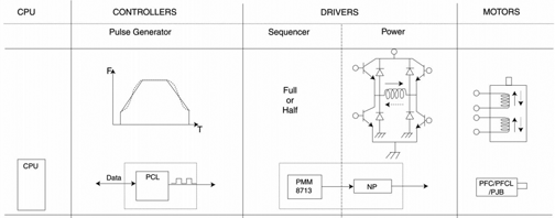
Fig. 1-Driving a step motor requires four parts: a CPU, controller, sequencer, and a driver.
The CPU will coordinate all functions of the device. The controller will take commands from the CPU and generate a pulse command telling the motor what to do. The sequencer will convert that pulse command to an excitation sequence telling the driver which phase of the motor to apply current and in which direction. The driver will take this information and drive the motor.
Depending on the components and complexity of the desired motion, one or more of these stages may be combined. First, though, let’s examine each stage.
Controllers
As seen in figure 2 a controller receives all feedback from the drive sensors and coordinates the motion with other system components.
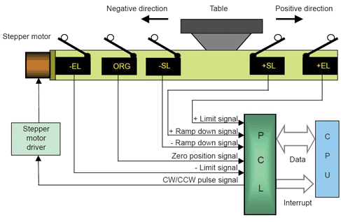
Fig. 2-Drive sensors send data to the controller, which coordinates the motion with other system components.
Controllers generate various motion profiles for smooth motor operation. Some controllers allow encoder feedback for motor speed, direction, and location. Some controllers also allow interpolation between two or more step motors to produce motions as shown in figure 3. This type of coordination is most commonly seen in XYZ stages like CNC machines.
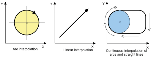
Fig. 3-Controllers generate motion profiles like these for smooth motor operation. Some controllers also allow interpolation between two or more stepper motors to produce motions typical for CNC machines.
There are two world standard outputs from controller to sequencer. One is called Pulse and Direction, and the other is called CW/CCW (see figure 4).
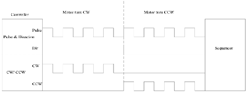
Fig. 4-Pulse and Direction and CW/CCW are two possible standard outputs from controller to sequencer.
As the name suggests, Pulse and Direction sends out a pulse that tells the speed, while direction tells the direction of rotation. CW/CCW sends out a pulse on one line telling speed for clockwise rotation and a pulse on the other line telling speed for counterclockwise rotation. Pulse and direction is the most common format used in the United States.
A sequencer will take the speed and direction information from the controller and create an excitation sequence as shown in figure 5 for bipolar systems. This sequence can then be connected to a driver to drive the step motor.

Fig. 5-Sequencers take the speed and direction information from the controller and create an excitation sequence that can be connected to a driver to drive the stepper motor.
Drivers
Drivers are dependant on the type of winding in your step motor. The windings come in two types: Bipolar and Unipolar. Each has advantages.
Bipolar.
The two-phase step sequence described earlier uses a “bipolar coil winding.” Each phase consists of a single winding. It is labeled a bipolar winding because the current flow on the coils is reversed, typically through an H-Bridge. By reversing the current in the windings, electromagnetic polarity is reversed (figure 6).
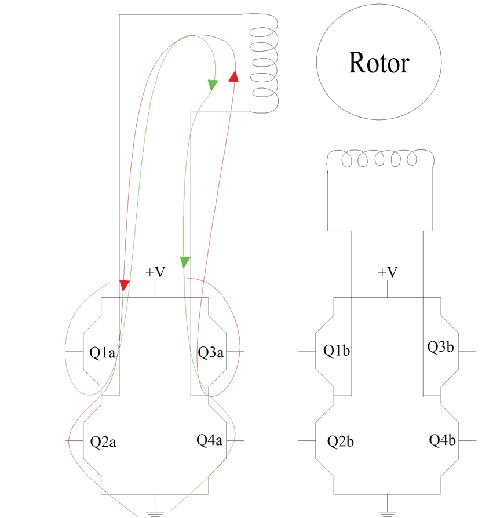
Fig. 6-In a bipolar winding the current flow on the coils can be reversed, typically through an H-Bridge, which reverses electromagnetic polarity. When Q1a and Q4a (green) are turned on, current flows in one direction. When Q2a and Q3a (red) are turned on, current flows in the other direction, reversing the current flow through the winding and changing the polarity of that phase.
When Q1a and Q4a (green) are turned on, current flows in one direction. When Q2a and Q3a (red) are turned on, current flows in the other direction, thus simply reversing the current flow through the winding and thereby changing the polarity of that phase.
Unipolar. This common winding is sometimes called four-phase stepper. It consists of two windings on a pole connected in such a way that when one winding is energized a magnetic north pole is created; when the other winding is energized, a south pole is created. It is referred to as a unipolar winding because the electrical polarity, or current flow, from the drive to the coils is never reversed.
Unipolar windings require half the drive electronics of bipolar windings. However, a unipolar winding has approximately 30% less torque available compared to a bipolar winding. The torque is lower because the energized coil only uses half as much copper as that of a bipolar coil.
On the other hand, the unipolar windings allow a higher pulse rate before becoming saturated because the unused windings act as a bleed off path for the electric energy (figure 7).
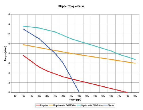
Fig. 7-Unipolar windings allow a high pulse rate before becoming saturated because the unused windings act as a bleed off path for the electric energy.
For each type of winding there are two different drivers available: Constant Current (CC) and Constant Voltage (CV). What we have discussed so far is the CV drive, which is fairly simple — just apply a voltage to a winding. The current is limited by the winding and Ohms law. One major disadvantage to CV drives is that the winding of a step motor is an inductor, and current lags voltage in an inductor.
When you apply voltage to the winding, it takes a little while for the full current to come through the windings, a feature to note because it is the current that generates torque in a step motor, not the voltage. As the motor moves faster, the width of the pulse gets smaller and less and less current is introduced in the winding. Thus, the motor produces less torque.
To handle this situation, engineers developed a constant current (CC) drive also known as PWM or chopper drive. It regulates current in much the same way that a switching power supply regulates voltage. A much higher voltage is applied to a winding through a switch, for example, 24 V is applied to a 5 V winding. A feed back circuit monitors the current through that winding. When this current hits a preset level, the voltage is switched off. When the current stored in the windings falls below a preset level, the voltage is switched back on. At lower switching speeds, there is not much difference between CV and CC but at higher switching speeds there is a big difference.
Stepping
So far, we have been talking only about full stepping. There are two types of full stepping: one called wave full step or 1-1 phase excitation, which was discussed in the first article. In 1-1 phase excitation only one phase of a step motor is excited at a time. Little current is used compared to other drive methods, but less torque is produced.
What most people call full stepping is called 2-2 phase excitation. In this type of stepping, two phases of the stepper motor are excited at all times. Microstepping can add some complexity to a step motor driver. Microstepping can be broken down into two categories: Half stepping and everything else.
The easiest way to accomplish half stepping is by using 1-2 phase excitation. This is the 1-1 and 2-2 full step method mixed. There is an off state inserted between transitioning phases. In Step 1, phase A of a two-phase stator is energized, magnetically locking the rotor, since unlike poles attract. When phase B is turned on, the rotor rotates 45° clockwise.
In Step 3, phase A is turned off, which causes another 45° rotation. In Step 4, phase A is turned on with polarity reversed from Step 1 and 2. Repeating this sequence causes the rotor to rotate clockwise in 45° steps. This cuts a stepper’s full step angle in half. However, half stepping typically results in a 30% loss of torque depending on step rate when compared to the two-phase on stepping sequence. Since one of the windings is not energized during each alternating half step there is less electromagnetic force exerted on the rotor resulting in a net loss of torque.
Microstepping allows a full step to be broken into as many as 256 parts. This is done by limiting the amount of current through each winding, which creates an unequal pull on the magnet, causing the magnet to pull towards the weaker of the two windings.
Microstepping has two main downfalls. Torque falls off fairly quickly as microstep rates increase. And the steps are not constant. Thus, microstepping should never be used to increase the resolution of a step motor.
The main reason for using microstepping is for a smoother and less noisy rotation of the motor. Step motors can have a jerky motion and be noisy at low speeds. Microstepping is most commonly handled with a CC drive although it can be done with a constant voltage drive.
Troubleshooting
Depending on the components and complexity of the desired motion, one or more of the stages mentioned above may be combined.
The CV drive is simple, just apply a voltage to a winding current, which is limited by the winding and ohms law. For unipolar motors, typically four power-mosfet’s are used as drivers. In this case, troubleshooting is fairly straight forward, since the excitation is applied to the gate of the mosfet’s.
The constant current (CC) drive adds a little more complexity, as does microstepping. A number of drive manufactures have simplified this situation by combining it all into one chip. One example is the Allegro 3967, it has combined the sequencer (translator) with the power driver (H-bridge) along with CC drive feedback/control (PWM timer) and microstepping (DAC).
In the last article, we spoke of step motors burning up. One of the most important characteristics of the step motor is that it can maintain the holding torque indefinitely when the rotor is stopped. If a step motor stalls out it will not typically burn up as with most ac and dc motors. If the motor does burn up it usually indicates a drive problem.
For example, consider a motor and drive with the current regulated to 300 mA at 24 V. Since the motor is rated for 300 mA everything is fine. If the regulator goes bad, however, we will have 1.6 A across the motor and it burns. Just replacing the motor will cause the motor to burn up again.
The sample schematic in figure 8 shows how this might look.
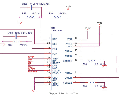
Fig. 8- If a step motor burns up, replacing it with the same type motor is not the answer. You need more information to determine why the motor is burning up. In this sample schematic, VBB is much higher than the rated voltage for the motor. The current limit is set by R82 and R83. By measuring voltage across R90 or R94 while the motor is powered up but not running, you can calculate the current flowing through them, and through each motor winding, which will tell you what you need to know to find a suitable replacement motor.
VBB is much higher than the rated voltage for the motor. The current limit is set by R82 and R83. By measuring voltage across R90 or R94 while the motor is powered up but not running, you can calculate the current flowing through them, and through each motor winding. With this current information, the motor’s resistance information, and Ohm’s law, you will have all information needed to replace the motor.
Example: The resistance across the motor mentioned earlier was 15 Ohms. I measures 333 mV drop across R90. Ohm’s law I=E/R says 0.333/1= 0.333 A or 333 mA, so 333 mA are flowing through the coils. E=I*R 0.333*15=4.995 or 5 V. Replacing the step motor with a 5 V Bipolar 15 Ohm, the motor should run without burning up. However, some manufacturers do slightly over power their step motors to get more torque out of them, and some under-power their stepper to produce less heat from the motor. Therefore, the next time you come across a step motor, you should know how to troubleshoot it.
Nippon Pulse America
www.nipponpulse.com
Filed Under: Motion control • motor controls, Motors • stepper

Tell Us What You Think!