A planetary gearbox offers high torque transmission with good stiffness and low noise, in a more compact footprint than other gearbox types.
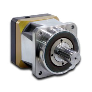
Image credit: Parker Hannifin Corp.
The planetary gearbox design is fairly simple, consisting of a central sun gear, an outer ring (also referred to as an internal gear because its tooth face inward) along with planetary gears and a carrier.
Input power to the sun gear causes it to spin. The planetary gears mesh with the sun gear, and as the sun gear spins, the planetary gears rotate on their axes. The planetary gears also mesh with the ring gear, which is stationary, causing the planetary gears to revolve around the sun gear. The carrier holds the planetary gears together and sets their spacing. It rotates with the planetary gears and incorporates the output shaft.
Planetary gears are also referred to as epicyclic gears. This video from Neugart GmbH demonstrates their construction and operation.
In a planetary gearbox, many teeth are engaged at once, which allows high speed reduction to be achieved with relatively small gears and lower inertia reflected back to the motor. Having multiple teeth share the load also allows planetary gears to transmit high levels of torque. The combination of compact size, large speed reduction and high torque transmission makes planetary gearboxes a popular choice for space-constrained applications.
But planetary gearboxes do have some disadvantages. Their complexity in design and manufacturing tends to make them a more expensive solution than other gearbox types. In addition, precision manufacturing is extremely important for these gearboxes. If one planetary gear is positioned closer to the sun gear than the others, imbalances in the planetary gears can occur, leading to premature wear and failure. Also, the compact footprint of planetary gears makes heat dissipation more difficult, so applications that run at very high speed or experience continuous operation may require cooling.
When using a standard (inline) planetary gearbox, the motor and the driven equipment must be inline with each other, although manufacturers offer right-angle designs that incorporate other gear sets (often bevel gears with helical teeth) to provide an offset between the input and output.
Planetary gearboxes can be constructed with either spur gears or helical gears. Spur gears have a zero helix angle, and therefore, produce no axial forces. So the bearings in a spur planetary gearbox only serve to support the gear shafts. Helical gears, in contrast, have a helix angle between 10 and 30 degrees, which causes them to generate significant axial forces. The bearings used in a helical planetary gearbox must withstand these axial forces. (Higher helix angles result in higher axial forces, but also provide higher torque capacity, less noise, and smoother operation.)
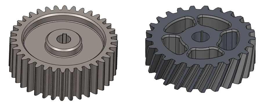
A spur gear (left) and helical gear (right).
Additionally, in a planetary gearbox — whether it is a spur design or a helical design — the bearings play an active role in torque transmission. But the planetary arrangement affords limited space within the gearbox to accommodate the bearings. Needle bearings are a good choice from a size perspective, but aren’t designed to withstand significant axial loads. Tapered roller bearings are suitable for high axial loads, but are generally larger than needle bearings.
The inherent limitations on bearing size and type, coupled with the dual task of transmitting torque and supporting axial loads, mean the torque ratings of helical planetary gearboxes can be lower than those of similar gearboxes using spur planetary gears, whose bearings only experience forces due to torque transmission (no axial loads). On the other hand, helical planetary designs have lower noise, smoother operation, and higher stiffness than spur planetary gearboxes. These attributes make helical planetary gearboxes the more common choice in servo applications.
Filed Under: Gears • gearheads • speed reducers, Motion control • motor controls, Motion Control Tips


Tell Us What You Think!