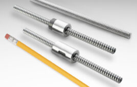
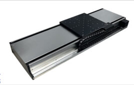
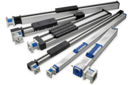
A ball screw spline is a combination of two components — a ball screw and a rotary ball spline. By combining a driving element (the ball screw) and a guiding element (the rotary ball spline), a ball screw spline can provide both linear and rotary motion, as well as spiral motion, in a highly rigid, compact design.
Components of a ball screw spline
Ball screw
A ball screw uses recirculating steel balls in a precisely machined nut to drive a load to an exact position. In most designs, the screw is fixed at one or both ends, and the nut is prevented from rotating via a keyed housing or other anti-rotation setup. A motor drives, or rotates, the screw. But because the screw is constrained from moving linearly, the motion is transferred to the ball nut, which travels along the length of the screw shaft.
Another ball screw design incorporates radial angular contact bearings on the outer diameter of the nut, allowing the nut to be driven — typically via a belt and pulley assembly connected to a motor — while the screw remains completely stationary. When the motor turns, it rotates the nut, causing it to traverse the length of the screw. This setup is commonly known as a “driven nut” design.

A “driven nut” design uses a belt and pulley connected to a radial bearing assembly on the outer diameter of the ball nut.
Image credit: SKF Group
Ball spline
A ball spline is a type of linear guide system similar to the round shaft and recirculating ball bearing, but with spline grooves precisely machined along the length of the shaft. These grooves prevent the bearing — referred to as a spline nut — from rotating, while also allowing the ball spline to transfer torque.
One variation of the standard ball spline is the rotary ball spline, which adds a rotating element — gears, crossed rollers, or angular contact ball bearings — to the outer diameter of the spline nut. This allows the rotary ball spline to provide both linear and rotational movement.
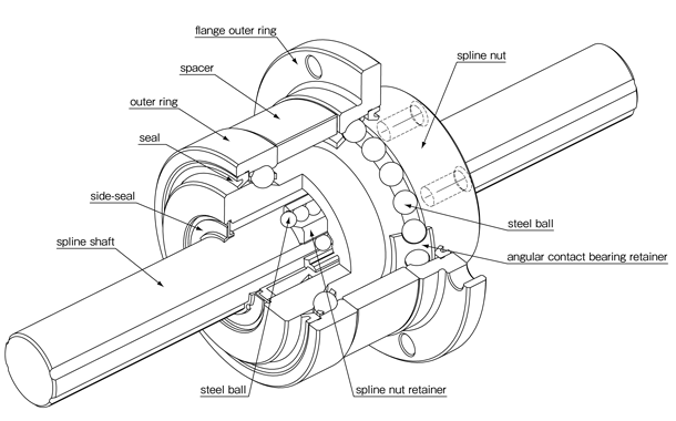
A rotary ball spline uses angular contact bearings (shown), crossed rollers, or gears on the outer diameter of the spline nut to produce rotary motion.
Image credit: NB Corporation of America
How a ball screw spline works
When a driven-nut type ball screw assembly is combined with a rotary ball spline, the resulting configuration is commonly referred to as a ball screw spline. The shaft of a ball screw spline has both screw threads and spline grooves along its length, with the threads and grooves “crossing” each other.
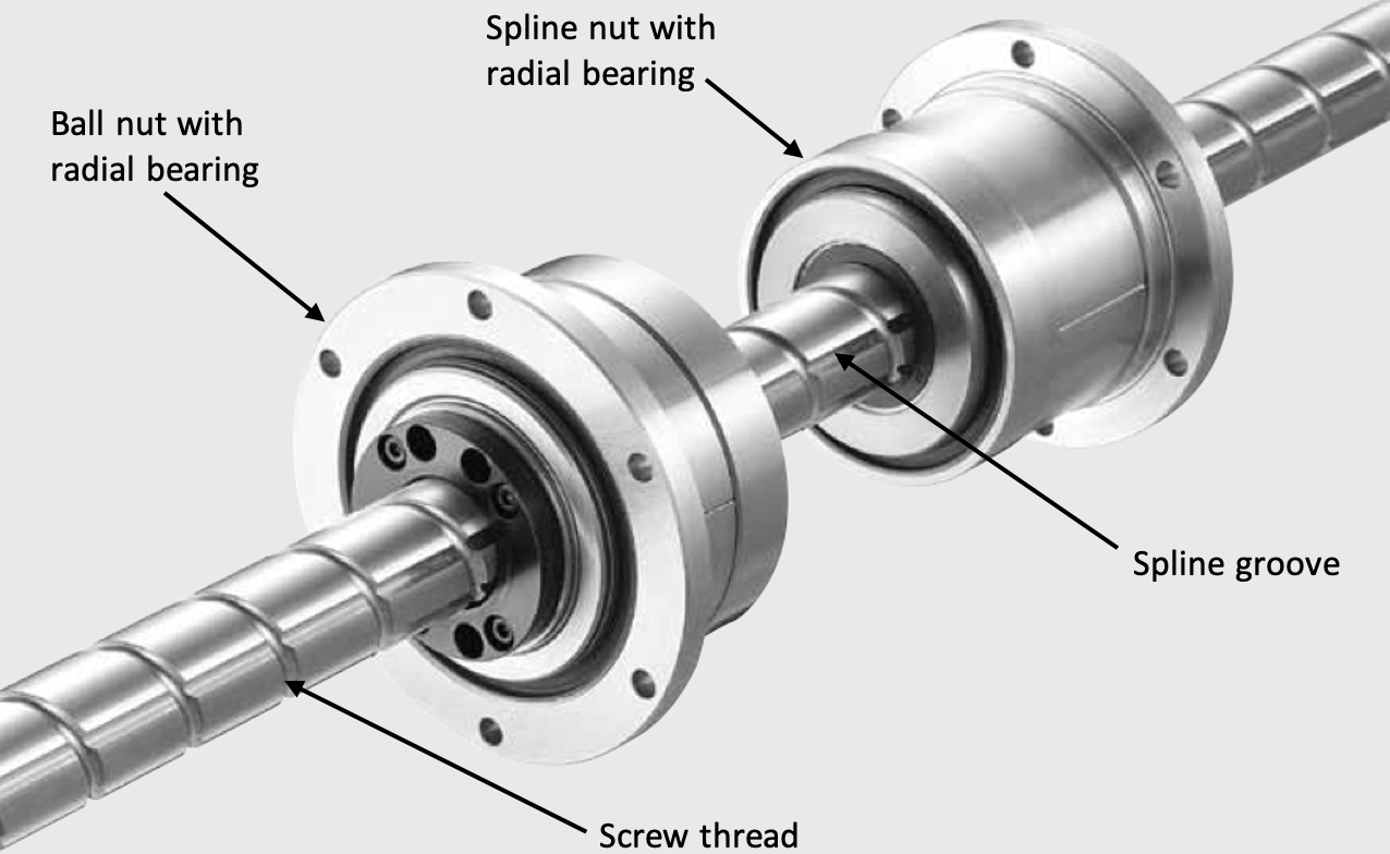
A ball screw spline has both a ball nut and a spline nut, each with a radial bearing on its outer diameter.
Image credit: Nippon Bearing
Three motions: linear, spiral, and rotary
Ball screw spline assemblies constrain both the ball screw nut and the ball spline nut from moving linearly. By driving the ball nut and the spline nut together or separately, three different types of motion can be produced: linear, spiral, and rotary.
To create linear motion, the ball nut is driven and the spline nut is held stationary. Since the ball nut cannot traverse linearly, the shaft traverses through the ball nut. However, the stationary spline nut keeps the shaft from spinning, so that the motion of the shaft is purely linear, with no rotation.
Alternatively, when the spline nut is driven and the ball nut is held stationary, the ball spline causes rotational motion, while the screw threads traveling through the stationary ball nut cause the shaft to travel linearly as it rotates, resulting in a spiral motion.
When both nuts are driven, the rotation of the ball nut essentially counteracts the linear motion caused by the ball spline, so the shaft rotates without any linear travel.
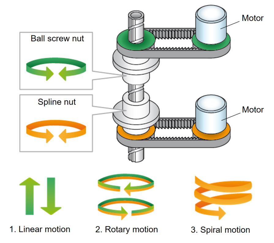
In a ball screw spline assembly, the ball screw nut and spline nut can be driven separately or together to produce linear, spiral, or rotary motion.
Image credit: THK
Filed Under: Linear Motion Tips


