It pays to know how RF can potentially garble the reception of signals such as those for WiFi, Bluetooth, and radar sensors.
We live in a world with an increasingly crowded radio frequency spectrum that is only likely to become more stuffed with RF signals. This is particularly true for the frequencies within the ISM spectrum bands originally reserved for industrial, scientific, and medical purposes. Now, of course, this part of the spectrum is employed by WiFi, Bluetooth, and numerous other emerging communication schemes. These systems are clustered around 2.4 GHz, but other bands are packed with signal sources as well. For example, LTE cellular operates with carrier frequencies typically below 2 GHz, while direct-broadcast satellites have a 12-GHz downlink and a 17-GHz uplink.
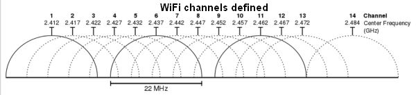
It’s easy to see the potential for interference when viewing the 16.25 to 22 MHz of channel separation used for WiFi channels. There’s a 2-MHz gap serving as a guard band between the channels. The reason is older routers with modem chip sets tended to transmit across the full channel. Though multiple WiFi transmitters at one location having overlapping frequencies will usually work, the overlapping transmissions can also cause interference resulting in slowdowns, sometimes severe, particularly in heavy use.
The potential for electromagnetic interference (EMI) is higher in circuitry operating in the gigahertz range partly because it can be tougher to squelch signal reflections at such high frequencies. To complicate matters, some countries are reassigning, for consumer use, parts of the spectrum now occupied by more specialized systems. The U.S. government, for example, aims to repurpose parts of the frequency spectrum to open up 500 MHz of new spectrum for mobile and broadband applications. Existing systems, beginning with those using the 1.755 to 1.850 GHz band, will have to move. The transition will likely happen over a multi-year period. During the shift, the potential for interference between the current and new systems is high.
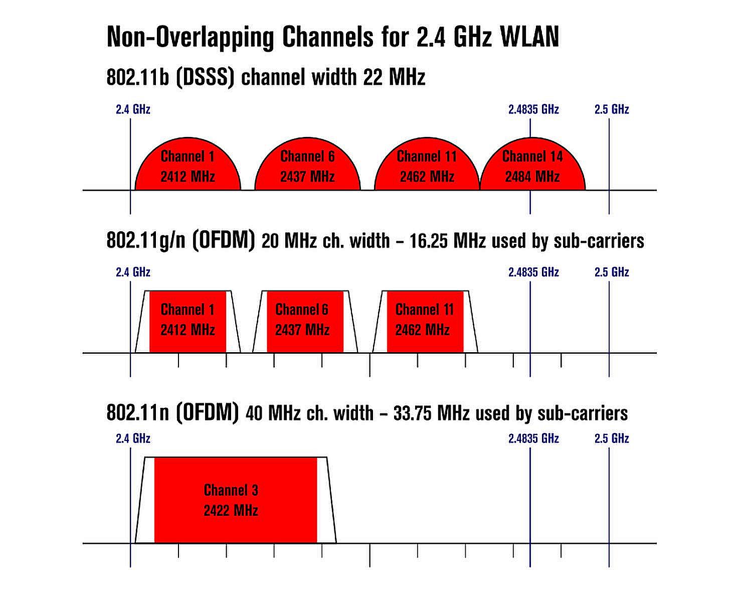
In 802.11 wireless protocols such as WiFi, certain subsets of frequencies can operate simultaneously at any one location without interference. But the exact frequency spacing necessary when the transmitters are not collocated depends on the protocol, the data rate, the distances involved and the electromagnetic environment. The overall effect is that adjacent-channel transmitters will often interfere with each other when there is a considerable overlap in their frequencies. The practice of using every fourth or fifth channel by leaving three or four channels clear between them can cause less interference than sharing channels.
To cite a specific example, the C band (between 3.7 and 4.2 GHz) has been used for more than 40 years by satellite operators for sending TV programming back to cable companies. One proposal is to reallocate the frequencies in the lower 200 MHz of the band so the upper 300 MHz can be auctioned to wireless carriers.
RF system standards aimed at consumer use typically build in some protection against interference. For example, IEEE 802.11-based systems typically try to avoid swamping out other signals by measuring channel energy before transmitting in a “listen before talk” protocol. Such features are helpful for reducing the chance of interference, but they are not a guarantee that trouble won’t arise.
Categorizing signals
It can be helpful to understand how interference sources can be categorized. The wireless industry groups interference into six general areas: in-band interference, co-channel interference, out-of-band interference, adjacent channel interference, downlink interference, and uplink interference. In-band interference covers undesired emissions from a transmitter that fall inside the operating bandwidth of the system at hand. This type of interference will pass through the receiver’s front end. There are challenges when the interference falls so close to the signal of interest.
If the amplitude of the interference is large relative to the desired signal, the desired signal will be corrupted. If the in-band interference amplitude is roughly that of the signal of interest, it may be tough to distinguish which is the interference and which is the signal. So it may be necessary to temporarily turn off the desired signal to quantify the interference.
When interference measurements take place in the field rather than in a test lab, it may not be possible to turn off the target transmitter. Here the usual practice is to physically move the test instrument (usually a spectrum analyzer) to where the amplitude of the interference is large enough to be measured. Use of a high-gain directional antenna can help pinpoint the interference source.
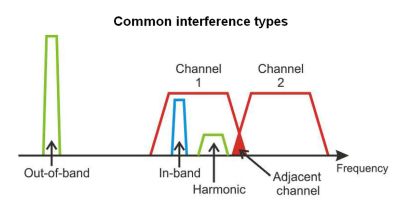
How types of interference are frequently classified. If Channel 1 represents the desired signal, the other signals shown here could degrade it. In-band, out-of-band (including its associated harmonic) and adjacent-channel interference (represented by the overlap between Channel 1 and Channel 2) may all interfere with the Channel 1.
Co-channel interference comes from another radio operating within the same wireless system. For example, cellular base stations will transmit on the same frequency channel when the base stations physically sit far apart. But occasionally the signal from one base station reaches a neighboring cell area. To the second base station, this signal is co-channel interference. Wireless LAN networks can also experience co-channel interference when two radios transmit simultaneously and collide in the same frequency channel. WLANs try to minimize this possibility by having WLAN transmitters listen for an open channel before transmitting, but there is a potential for simultaneous transmissions nevertheless.
Co-channel interference is one of the most common types of radio interference because large numbers of wireless users occupy relatively few frequency channels. The usual way of observing co-channel interference is to shut off the transmitter of interest and tune a spectrum analyzer to the appropriate frequency channel.
Out-of-band interference originates from a wireless system that — due to improper filtering, non-linearity and/or signal leakage — also transmits energy in a frequency band outside that of its intended use. An example is when a poorly designed or poorly filtered transmitter radiates harmonics that fall into a higher frequency band.
The measurement of harmonic levels generally takes place using a spectrum analyzer with a frequency range of at least three times the fundamental of the harmonics. For example, consider the case of verifying the performance of a transmitter operating at 802.11b channel 14, 2.4835 GHz. The second and third harmonics are at 4.967 and 7.4505 GHz, respectively. The measuring instrument must have a bandwidth exceeding about 7.5 GHz to see these harmonics.
Adjacent channel interference results when a transmission at the desired frequency channel produces unwanted energy in other nearby channels. This type of interference is common and primarily created by energy splatter out of the assigned frequency channel and into the surrounding upper and lower channels. Energy splatter (also called switch noise) refers to spurious emissions resulting from an abrupt change in the transmitted signal, usually when transmission starts or stops. It can also be generated by modulation and intermodulation distortion.

The second through fourth-order intermodulation products that arise when two frequencies f1 and f2 intermodulate.
Intermodulation distortion, or spectral re-growth, is the amplitude modulation of signals containing two or more different frequencies, caused by nonlinearities in the circuitry. It is often created in the transmitter’s power amplifier because of nonlinear effects in the power electronics.
Passive components–including antennas, cables and connectors–can also produce intermodulation interference. Often referred to as passive intermodulation (PIM), it can happen in passive components excited by two or more high-power signals. A circuit having non-linear characteristics can distort the fundamental frequency components and generate a decaying series of higher-order harmonic frequency components. These generated harmonics can be problematic if they fall within the reception band of the system of interest. If they are big enough, they can effectively block a channel by making a receiver think a carrier is present when one is not.
Generally, the components of concern are the third, fifth, and seventh order where the third order is strongest. To understand where intermodulation frequencies might crop up, suppose the fundamental frequencies are f1 and f2, and the sum of m and n is the product order. The intermodulation products are given by (mf1-nf2) and (mf2-nf1). So, for example, there are two third-order intermodulation products: m=1 and n=2, and m=2 and n=1. Thus, the possible third-order intermodulation products would be (2f1-f2) and (2f2-f1).
Major causes of PIM in passive devices include poor contact junctions, contamination, and materials or plating that will exhibit some level of hysteresis. Contact nonlinearities arise when current-carrying contacts become separated. Typical causes are insufficient contact pressure, irregular contact surfaces, oxidation causing a metal/oxide junction, as well as contact impurities or corrosion. Minute separation between contact surfaces can generate a voltage potential where electron tunneling (known as the diode effect) or microscopic arcing may cause a nonlinear voltage-to-current ratio. Ferromagnetic materials, such as nickel or steel, in the current path can also generate the nonlinear voltage-to-current ratio. Another source of intermittent nonlinearities are contaminants such as metal particles from machining that touch current-carrying surfaces.
Downlink and uplink interference are terms typically associated with mobile phones and satellites. Downlink interference can corrupt the downlink connection typically between a base transceiver station (BTS) and a mobile device. Mobile devices are usually widely spaced, so downlink interference typically only affects a few of them and only minimally degrades the communication quality of the system as a whole. It should be noted that downlink interference is also cochannel interference.
Finally, uplink interference or reverse-link interference affects communications sent from the mobile device to the BTS receiver or from a base station back to a satellite. In cellular networks, uplink interference determines the capacity of each cell site. If the BTS is compromised, the cell site service area may see degraded performance.
Measurement considerations
There are several instrument qualities besides simple bandwidth that affect the degree to which interfering signals can be viewed. Perhaps most important is what’s often called the instrument’s resolution bandwidth (RBW) setting. This is a measure of the minimum separation between two frequency components necessary for them to appear as separate signals on the screen.

Spectrum analyzers incorporate several features that can be helpful in finding sources of EMI. One example is MaxHold display mode found in the FieldFox spectrum analyzers from Keysight Technologies. In this mode, the analyzer can store and display the maximum trace values over multiple sweeps. This example shows a measurement of a frequency hopping carrier with the analyzer configured with two active traces. Trace 1 (yellow) is configured with the MaxHold mode while trace 2 (blue) is the standard sweep “clear/write” (Clr/Wr) mode. After several sweeps, the MaxHold trace is relatively stable but the Clr/Wr trace reflects the frequency hopping signal’s constantly changing nature. A second carrier, visible at the left, is a fixed-frequency signal that could represent a source of interference to the hopping signal when the two signals eventually collide.
Typically, the measurement instrument’s noise floor, sometimes referred to as Displayed Average Noise Level (DANL), is lowest with narrow RBW settings. The trade-off is that narrow RBW settings slow the analyzer sweep time, particularly for wide frequency ranges common to harmonic testing.
In general, over-the-air measurements of interference typically demand use of a spectrum analyzer having a low DANL. A rule of thumb is that reducing RBW by a factor of ten will lower the noise floor by about 10 dB. Because the analyzer measurement sweep time is an inverse function of the RBW, smaller RBW settings force longer sweep times.
Another point to note is that low-level signal display is a function of the signal-to-noise ratio (SNR) at the detector of the analyzer. Thus, though it may seem obvious, reducing the amount of input attenuation can improve the signal level. The measured signal level at the detector may also be improved through use of an external preamplifier. The downside of reducing the input attenuation is that large-amplitude signals can overdrive the analyzer front end, causing internally generated distortion and harmonics. These internally generated signals can appear as though they are part of the signal of interest. Thus, it’s important the attenuator setting is low enough to display low-level interference but not so low that it causes problems when anticipated high-amplitude signals are present. DW
You may also like:


Filed Under: Wireless • 5G and more