Design World

  • Home
  • Technologies
    • 3D CAD
    • Electronics • electrical
    • Fastening & Joining
    • Factory automation
    • Linear Motion
    • Motion Control
    • Test & Measurement
    • Sensors
    • Fluid power
  • Learn
    • Ebooks / Tech Tips
    • Engineering Week
    • Future of Design Engineering
    • MC² Motion Control Classrooms
    • Podcasts
    • Videos
    • Webinars
  • LEAP AWARDS
  • Leadership
    • 2022 Voting
    • 2021 Winners
  • Design Guide Library
  • Resources
    • 3D Cad Models
      • PARTsolutions
      • TraceParts
    • Digital Issues
      • Design World
      • EE World
    • Women in Engineering
  • Supplier Listings

FAQ: What do 1X, 2X, and 4X position encoding mean for incremental encoders?

By Danielle Collins | October 1, 2015

Share

An encoder is a device that measures position, and in some configurations, can also measure direction. Rotary encoders measure rotation of a shaft, while linear encoders measure distance traveled. For both types of encoder, the position measurement can be either incremental or absolute. An incremental encoder measures change in position, but does not keep track of actual position. When power is interrupted, incremental encoders lose their position reference and must start over via a re-homing sequence to a reference point. Absolute encoders, on the other hand, keep track of absolute position, whether rotation of a shaft or linear travel, by assigning a unique digital value to each position. So even if power is lost, an absolute encoder will know the exact position of the shaft or the linear drive.

Incremental encoders work by producing a specific number of equally spaced pulses per revolution (PPR) or per distance (PPM—pulses per millimeter, or PPI—pulses per inch). When one set of pulses, or output channel, is used, the encoder can determine position only.  But most incremental encoders use quadrature output, which consists of two channels, typically referred to as channel A and channel B, that are out of phase by 90 degrees. Quadrature output allows the encoder to also sense direction, by determining which channel is leading and which is following. Some incremental encoders also produce a third channel with a single pulse, commonly referred to as channel Z or channel I. This channel serves as the index or reference position for homing.

With quadrature output, three types of encoding can be used: X1, X2, or X4. The difference between these encoding types is simply which edges of which channel are counted during movement, but their influence on encoder resolution is significant.

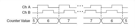
With X1 encoding, either the rising (aka leading) or the falling (aka following) edge of channel A is counted. If channel A leads channel B, the rising edge is counted, and the movement is forward, or clockwise. Conversely, if channel B leads channel A, the falling edge is counted, and the movement is backwards, or counterclockwise.

Incremental encoders


When X2 encoding is used, both the rising and falling edges of channel A are counted. This doubles the number of pulses that are counted for each rotation or linear distance, which in turn doubles the encoder’s resolution.

Incremental encoders


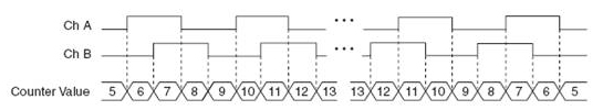
X4 encoding goes one step further, to count both the rising and falling edges of both channels A and B, which quadruples the number of pulses and increases resolution by four times.

Incremental Encoders


For rotary encoders, position is calculated by dividing the number of edges counted by the product of the number of pulses per revolution and the encoding type described above (1, 2, or 4), and then multiplying the result by 360 in order to get degrees of motion.

Incremental Encoders

x = type of encoding (X1, X2, or X4)

N = number of pulses generated per shaft revolution

For linear encoders, position is calculated by dividing the number of edges counted by the product of the number pulses per revolution and the encoding type. This result is then multiplied by the inverse of the pulses per millimeter (or per inch).

Incremental encoders

incremental encoders

PPM = pulses per millimeter

PPI = pulses per inch

Incremental encoders are a relatively simple and inexpensive feedback option for applications where re-homing after a power loss is not detrimental to the process. And with quadrature output, incremental encoders can achieve high resolution, even at high speeds.


Featured image credit: National Instruments Corporation

Motion Control Tips


Filed Under: Motion Control Tips, Encoders • linear, Encoders (rotary) + resolvers, Motion control • motor controls
Tagged With: ni, nationalinstruments
 

About The Author

Danielle Collins

Related Articles Read More >

Automation 1 Family and iXC4e
Aerotech continues development of Automation1 motion control platform
Motion & Control Enterprises purchases RSA and Global Controls, fourth acquisition this year
49503-ACS Motion-CMxa
ACS Motion Control releases SPiiPlusCMxa EtherCAT motion controller
SDP-SI-040
SDP/SI launches brushless DC motors and motion control products series

DESIGN GUIDE LIBRARY

“motion

Enews Sign Up

Motion Control Classroom

Design World Digital Edition

cover

Browse the most current issue of Design World and back issues in an easy to use high quality format. Clip, share and download with the leading design engineering magazine today.

EDABoard the Forum for Electronics

Top global problem solving EE forum covering Microcontrollers, DSP, Networking, Analog and Digital Design, RF, Power Electronics, PCB Routing and much more

EDABoard: Forum for electronics

Sponsored Content

  • Renishaw next-generation FORTiS™ enclosed linear encoders offer enhanced metrology and reliability for machine tools
  • WAGO’s smartDESIGNER Online Provides Seamless Progression for Projects
  • Epoxy Certified for UL 1203 Standard
  • The Importance of Industrial Cable Resistance to Chemicals and Oils
  • Optimize, streamline and increase production capacity with pallet-handling conveyor systems
  • Global supply needs drive increased manufacturing footprint development

Design World Podcasts

June 12, 2022
How to avoid over engineering a part
See More >
Engineering Exchange

The Engineering Exchange is a global educational networking community for engineers.

Connect, share, and learn today »

Design World
  • Advertising
  • About us
  • Contact
  • Manage your Design World Subscription
  • Subscribe
  • Design World Digital Network
  • Engineering White Papers
  • LEAP AWARDS

Copyright © 2022 WTWH Media LLC. All Rights Reserved. The material on this site may not be reproduced, distributed, transmitted, cached or otherwise used, except with the prior written permission of WTWH Media
Privacy Policy | Advertising | About Us

Search Design World

  • Home
  • Technologies
    • 3D CAD
    • Electronics • electrical
    • Fastening & Joining
    • Factory automation
    • Linear Motion
    • Motion Control
    • Test & Measurement
    • Sensors
    • Fluid power
  • Learn
    • Ebooks / Tech Tips
    • Engineering Week
    • Future of Design Engineering
    • MC² Motion Control Classrooms
    • Podcasts
    • Videos
    • Webinars
  • LEAP AWARDS
  • Leadership
    • 2022 Voting
    • 2021 Winners
  • Design Guide Library
  • Resources
    • 3D Cad Models
      • PARTsolutions
      • TraceParts
    • Digital Issues
      • Design World
      • EE World
    • Women in Engineering
  • Supplier Listings