Design World

  • Home
  • Technologies
    • 3D CAD
    • Electronics • electrical
    • Fastening & Joining
    • Factory automation
    • Linear Motion
    • Motion Control
    • Test & Measurement
    • Sensors
    • Fluid power
  • Learn
    • Ebooks / Tech Tips
    • Engineering Week
    • Future of Design Engineering
    • MC² Motion Control Classrooms
    • Podcasts
    • Videos
    • Webinars
  • LEAP AWARDS
  • Leadership
    • 2022 Voting
    • 2021 Winners
  • Design Guide Library
  • Resources
    • 3D Cad Models
      • PARTsolutions
      • TraceParts
    • Digital Issues
      • Design World
      • EE World
    • Women in Engineering
  • Supplier Listings

How to calculate retaining ring maximum speed (rpm), and when it matters

By Danielle Collins | February 25, 2022

Share

Selecting an appropriate retaining ring for an application typically involves evaluating factors such as installation stress, the radial load exerted by the ring, and the thrust capacity of the ring. And because the groove that holds the ring is integral to the ring’s performance, groove deformation needs to be considered as well.

application
Image credit: G.L. Huyett

But when an external retaining ring is used on a rotating shaft, centrifugal forces can cause the ring to lift out of its groove, leading to ring failure, so maximum speed becomes an important selection factor as well.

high speed retaining ring
To withstand high speeds and centrifugal forces, this retaining ring has a “self-locking” mechanism consisting of a dome and a slot, which limits how far the ring can expand.
Image credit: Smalley

The maximum speed that an external retaining ring can withstand is the speed at which the force holding the ring in its groove becomes zero, and is determined by the ring’s material properties and size.

retaining ring max speed equation

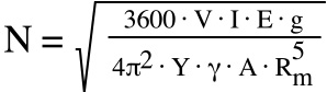
N = maximum rotational speed (rpm)

3600 = conversion from rotations per second to rotations per minute (square root of 3600 = 60)

V = radial interference between ring and groove, also referred to as “cling” (in)

radial interference equation

DG = groove diameter (in)

DI = ring inside diameter (in)

I = planar moment of inertia (in4)

Because the ring has a rectangular cross section, we use the planar moment of inertia (also referred to as second moment of area) formula for a rectangle, using the ring’s thickness and section width as the base and height of the rectangle.

planar moment of inertia equation

t = ring thickness (in)

b = ring radial section width, or wall (in)

E = modulus of elasticity (psi) = 29 x 106 psi (for most steels, excluding stainless alloys)

g = acceleration due to gravity (in/s2) = 386.4 in/s2

4π2 = factor to convert to revolutions (square root of 4π2 = 2π, which is the number of radians in one revolution)

Y = factor for number of turns (1 turn = 1.909, 2 turns = 3.407, 3 turns = 4.958)

Spiral retaining rings can have more than one turn, or coil, around the ring’s diameter. Typical constant section and tapered rings have only one turn, so for these designs, the factor for one turn (1.909) is used.

γ = material density (lb/in3) = 0.283 lb/in3 (for most steels, excluding stainless alloys) 

A = cross-sectional area (in2)

area equation

Rm = mean free radius (in)

retaining ring mean free radius equation


For retaining rings made of most steels and steel alloys, except stainless versions, the known quantities can be combined, and the equation can be simplified to:

retaining ring max speed equation

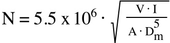
Note that in the denominator, we’ve used mean diameter, rather than the mean radius.

retaining ring mean free diameter equation

Dm = mean free diameter (in)

interlocking retaining ring
Here, two halves interlock when assembled to prevent the ring from expanding in high-speed operation.
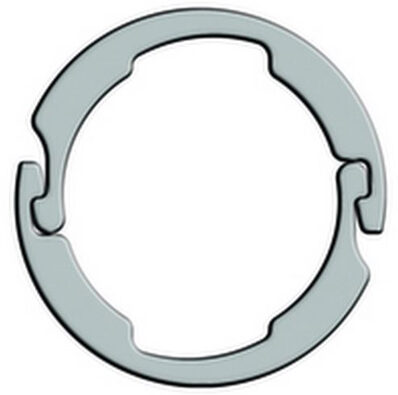
Image credit: Rotor Clip

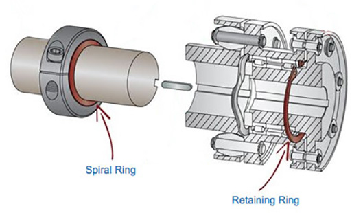
To address applications that run at high speed, retaining ring manufacturers have developed external rings with self-locking features that prevent the ring from failing, even under high centrifugal forces.

One design, used for spiral-wound retaining rings, incorporates a raised dome on the inside turn of the ring and a slot on the outside turn. As speed increases and the ring begins to expand, the dome slides along the slot, and the length of the slot limits the amount by which the ring can expand. Another design, used on traditional retaining rings, features a two-piece ring whose ends interlock when assembled onto a shaft, preventing the ring from expanding.


Filed Under: Uncategorized


Related Articles Read More >

54879_Network shares according to HMS 2022
Industrial networks keep growing despite challenging times
ABB_e-Configure
Device Data: do-it-yourself is history
AutomationDirect-Fath
FATH T-Slotted rail hardware from AutomationDirect
eSIGN_3
New eSIGN signal tower from WERMA

DESIGN GUIDE LIBRARY

“motion

Enews Sign Up

Motion Control Classroom

Design World Digital Edition

cover

Browse the most current issue of Design World and back issues in an easy to use high quality format. Clip, share and download with the leading design engineering magazine today.

EDABoard the Forum for Electronics

Top global problem solving EE forum covering Microcontrollers, DSP, Networking, Analog and Digital Design, RF, Power Electronics, PCB Routing and much more

EDABoard: Forum for electronics

Sponsored Content

  • Global supply needs drive increased manufacturing footprint development
  • How to Increase Rotational Capacity for a Retaining Ring
  • Cordis high resolution electronic proportional pressure controls
  • WAGO’s custom designed interface wiring system making industrial applications easier
  • 10 Reasons to Specify Valve Manifolds
  • Case study: How a 3D-printed tool saved thousands of hours and dollars

Design World Podcasts

May 17, 2022
Another view on additive and the aerospace industry
See More >
Engineering Exchange

The Engineering Exchange is a global educational networking community for engineers.

Connect, share, and learn today »

Design World
  • Advertising
  • About us
  • Contact
  • Manage your Design World Subscription
  • Subscribe
  • Design World Digital Network
  • Engineering White Papers
  • LEAP AWARDS

Copyright © 2022 WTWH Media LLC. All Rights Reserved. The material on this site may not be reproduced, distributed, transmitted, cached or otherwise used, except with the prior written permission of WTWH Media
Privacy Policy | Advertising | About Us

Search Design World

  • Home
  • Technologies
    • 3D CAD
    • Electronics • electrical
    • Fastening & Joining
    • Factory automation
    • Linear Motion
    • Motion Control
    • Test & Measurement
    • Sensors
    • Fluid power
  • Learn
    • Ebooks / Tech Tips
    • Engineering Week
    • Future of Design Engineering
    • MC² Motion Control Classrooms
    • Podcasts
    • Videos
    • Webinars
  • LEAP AWARDS
  • Leadership
    • 2022 Voting
    • 2021 Winners
  • Design Guide Library
  • Resources
    • 3D Cad Models
      • PARTsolutions
      • TraceParts
    • Digital Issues
      • Design World
      • EE World
    • Women in Engineering
  • Supplier Listings