Novel axial flux designs now coming off the drawing boards could become the primary means of powering future generations of electric vehicles.
Leland Teschler | Executive Editor
If you build an electric motor whose rotor and stator are flat, not cylindrical as in ordinary motors, you are devising what’s called an axial motor. Axial motors, as their name suggests, produce flux in an axial, rather than radial, airgap. The resulting envelope for the motor can be disc-shaped. This short, stubby profile makes axial motors good candidates for use in cramped quarters such as the recess of an automotive wheel hub.
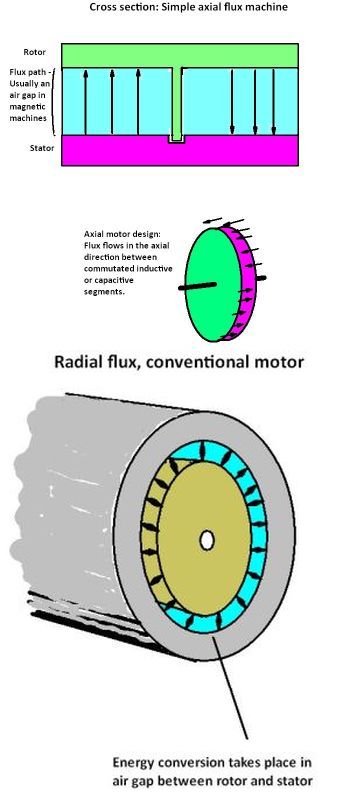
A key advantage of an axial-flux motor is the large amount of motor area it devotes to energy conversion compared to that of a conventional radial-flux motor. In radial-flux machines, energy conversion takes place in the cylindrical air gap between the rotor and stator. Power scales up with the square of the motor diameter. But power scales up in an axial-flux motor at a rate somewhere between the second and third power of motor diameter thanks to the larger energy conversion area.
Axial flux magnetic machines can produce a higher torque than a conventional motor of the same size. The reason is that magnetic flux in a conventional radial motor scales with the square of the diameter, but flux in an axial machine scales with between the second and third power. So the bigger the motor, the larger the advantage of an axial design.
Motors with an axial form factor have gotten a lot of attention in recent years as the move toward electric vehicles has fostered a need for small, compact powertrains. New axial designs have been proposed for use in drones, robotics, and other applications where space-efficient power is a benefit.
It can be useful to study specific axial designs as a way to understand how these motors operate. One of the more interesting examples of the technology is what’s called an electrostatic motor, devised by C-Motive Technologies Inc. Rather than use magnetic attraction to spin a rotor, the C-Motive machine uses an electric field. In addition to the advantages of an axial design, the C-Motive electric field devices are lighter and smaller than magnetic devices of similar output parameters.
Motors that use an electric field for motive force are built around the idea of spinning capacitors rather than the spinning inductors of conventional electromagnetic designs. Energy conversion in conventional magnetic motors takes place in the air gap between the rotor and stator. In contrast, energy conversion in electric field-powered motors takes place in a dielectric material. Electric field-powered motors have only become practical in recent years with the development of dielectric materials having a high electric permittivity. Their novel architecture combined with other advances lets these motors store 45,000 times more energy than possible previously.
The main factor determining the efficiency of electric power mechanisms for energy conversion is the density of the electric or magnetic energy stored in the electromagnetic or electric fields. The fact that electric field machines can be smaller and lighter than magnetic versions can be explained partly by the configuration of magnetic force lines. They form in the heavy electric steel in the motor. The magnetic circuit is used for power transfer, but energy conversion takes place in the air-gap itself between the stator and the rotor. And the air-gap volume accounts for a relatively small part of the machine’s volume. The electrical steel takes up most of the space.
In contrast, electric field machines have power lines starting and ending in the rotor and stator plates. Energy conversion takes place in the gap between the stator and rotor. But the rotor-stator gap takes up a sizable part of the volume of the whole machine. Assuming that the specific energy is equal for both electric field and electromagnetic machines, the machines based on the electric field effect will be significantly smaller. Because dielectric materials are much lighter than ferromagnetic materials, machines based on the electric field effect will be also lighter and likely less expensive.
To understand how a motor can be devised using capacitors, consider a round capacitor with each of its two plates divided into two or more sectors. The rotor sectors have a constant electrical charge of alternating polarity. The stator sectors have time-varying ac charges.
When a voltage is applied across this capacitor, there is an attractive force between the stator and rotor sectors. If the rotor and stator sectors are offset from one another, the attractive force establishes a moment. The moment rotates the rotor until the sectors coincide.
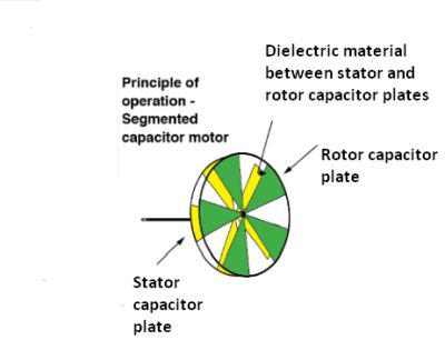
The concept of a capacitive motor can be understood by visualizing two segmented discs rotating near each other, separated by a dielectric. Each segment of the disc forms one plate of a capacitor. The motor shaft can be rotated by energizing one set of plates that are offset from one another, then switching the polarization as the plates approach complete overlap in a manner that resembles commutation in conventional dc motors.
At the moment the sectors coincide, the polarity of the applied voltage is switched between the positively and negatively charged sectors. The action is analogous to that of commutation for dc motors. If the number of plates rises, the motor torque increases.
The torque of a capacitive machine operating this way can be calculated by differentiating the energy stored in the capacitor electric field. Motor designers can boost the torque the motor can provide by increasing the number of rotor-stator capacitors. Of course, as the rotor spins, the capacitance between the rotor and the stator varies in proportion to how much their surfaces coincide. But the moment of this capacitive machine is constant and independent of the rotor angle. The speed of the capacitive motor is a function of the supplied power.
Shades of Ben Franklin
The idea of a capacitive motor created this way is quite old – Ben Franklin devised one in the 1750s. But the concept has only recently been realized in motors practical for real use.
One such design comes from C-Motive Technologies Inc. in Madison, Wisc. C-Motive calls its design an electrostatic motor. It’s biggest innovation, according to C-Motive CEO Justin Reed, is a dielectric in the form of a liquid that lies between the capacitor plates that make up the stator and rotor. “People have assumed the viscous drag of a liquid dielectric would be too high. But we’ve figured out a way to manage the viscous drag,” Reed says. “The resulting electrostatic motor produces high levels of torque that are superior to what rare-earth PM motors produce on a torque-per-kilogram basis.”
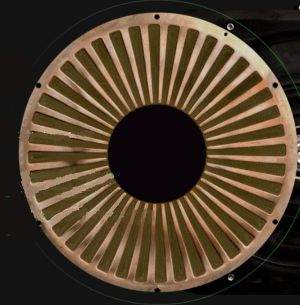
Visible on this stator from a C-Motive electrostatic motor are the segments making up the stator capacitor plate. The rotor capacitor plate would look identical though it would be attached to the shaft that rotates. C-Motive says the stator and rotor capacitor plates are on conventional FR4 printed circuit board material. The large number of plate segments are indicative of the large number of poles that characterize the company’s motors.
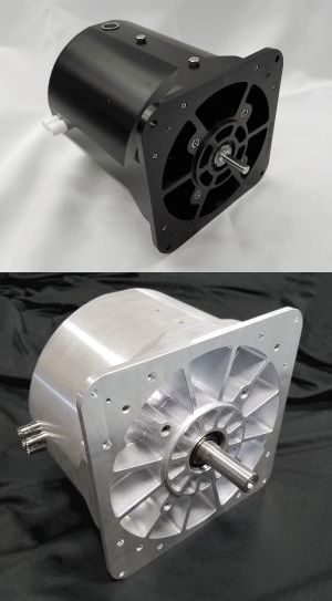
Prototype electrostatic axial motors from C-Motive. The company says the motors are under consideration for a number of applications. C-Motive also says the typical drive circuit for these motors would be relatively ordinary medium-voltage, low-current inverter.
Reed also says it is relatively easy to cool the C-Motive motor because its dielectric fluid conducts heat to the enclosure. This factor additionally lets the motor be sealed if necessary, to handle harsh environments with no degradation of its cooling capacity.
Reed thinks the operational sweet spot for the electrostatic motor will be applications in the 2,000-rpm range and below. “For all intents and purposes the only loss in the machines is the viscous drag. The drag will keep them out of areas that need 15,000 rpm motors,” he says. “The slower it spins, the more efficient it becomes. That’s the opposite of any electromagnetic motor.”
Reed says the electrostatic motor is in the development phase with the first full prototype expected early next year. The prototype will be a NEMA 56 frame servomotor meant as a demonstrator. Companies in a number of industries have expressed interest in seeing the prototype, he says, for applications such as wheel hub motors in off-road vehicles, three wheelers, and aerial drones. Larger aerial drone uses are particularly well-suited for the motors, he thinks, because they are characterized by slower-spinning props that would otherwise require conventional motors that could become quite heavy.
Axial axioms
Another example of an axial motor design comes from Magnax in Belgium. Its axial flux design is based on a proof-of-concept originally built at the University of Ghent in 2009. The motor uses a stator disc carrying windings that is sandwiched between two rotor discs carrying magnets. There are small air gaps between the stator and two rotors. The stator has a special design that is termed yokeless because it includes iron teeth carrying windings but without using an outer iron section to hold the teeth. This gives the motor a shorter flux path. The windings around the teeth are positioned such that there are no overhanging loops that don’t contribute to generating flux. Thus in the Magnax axial motor, 100% of the windings are active. Ordinary radial flux motors might only have 50% of their winding wire contributing to the generation of magnetic flux, adding extra resistance and causing heat build-up. Magnax further boosts motor efficiency through use of rectangular-section copper wire.
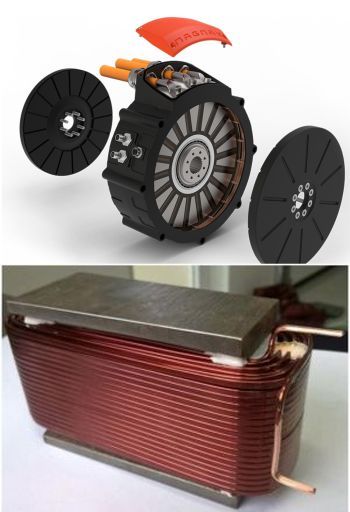
The axial magnetic motor from Magnax in Belgium sandwiches the stator windings between two rotors carrying rare-earth magnets. The motor design is called yokeless because each stator winding (visible in the close up at bottom) sits in the magnetic field of the rotor magnets without the use of metal pieces forming a yoke.
The point of the yokeless design is to help maintain a constant air gap between the stator and rotor. Other magnetic axial motors tend to generate enough force between the rotor and stator discs to actually deflect the rotor against the stator and cause a failure.
As Magnax describes it, the yokeless axial flux design is such that the two rotor discs constantly put equal and opposing forces onto the stator disc. The rotors connect directly to one another via a shaft ring, so the magnetic forces cancel each other out leaving no loads on the internal bearing.
To help cool the motor, Magnax brings the windings into direct contact with the outer aluminum casing for better heat transfer.
Magnax says its motor is highly scalable, ranging in diameters from 15 cm (~6 in.) to 5.4 m (~13 ft) and perhaps beyond. The motors can also be slotted in next to one another to run in parallel. Typical applications might include EVs, aircraft rotors, and in large-diameter, high-torque, low-RPM wind power, hydroelectric and wave power generation. DW
You may also like:


Filed Under: Bearings, Capacitors, MOTION CONTROL, Motion control • motor controls, Power Electronic Tips


