Edited by: Paul J. Heney, Editorial Director
In a vacuum system, the difference between atmospheric and vacuum pressure creates the ability to lift, hold, move and perform work.
There are two types of systems, porous (or open) and non-porous (or closed). Each has a logical progression that occurs when designing. It is important to follow this progression, as there are a number of considerations that will impact on the success or failure of the system.

Non-porous systems
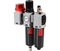
The first type of vacuum system is non-porous. Designing this system is straightforward. There are three basic considerations: volume, vacuum level and speed of evacuation. Other considerations include controls for signaling, energy saving devices, and filtration. An example of this type of application is a reservoir or vacuum tank.
To begin a design of this nature, it is necessary to know the total volume to be evacuated. This includes the tank, vacuum line or connection and filter. The second consideration is the level of vacuum necessary. Whether you plan to use a mechanical or air driven pump, different units perform differently, and some types are more suitable than others. The third consideration is the speed of evacuation. Vacuum flow determines the speed of a pump. The more free air a unit can process, the faster the evacuation. Volume and level of vacuum are determining factors here in that the deeper the required level of vacuum, and the greater the volume to be evacuated, the longer it will take to achieve.
Line size is extremely important if the pump and system are to perform as designed. As mentioned, vacuum flow is the determining factor. Line size determines how much flow actually flows. If a vacuum line is too small, the flow is restricted; too large and unnecessary additional volume is added. A rule of thumb to operate by is that the size of a vacuum line should be equal to the size of the vacuum port on the pump.

Once the volume, speed and level are achieved, ancillary factors such as controls and filtration factor in. A vacuum switch that signals a valve once the pre-determined level of mercury is achieved is one type of control that could be used. A mechanical pump might require a vacuum valve between the pump and tank that closes once a certain level of vacuum is reached. The pump continues to operate, but the valve shifts, opening to atmosphere. This prevents the pump from overheating by pumping against a closed valve. The valve for an air driven system is placed on the air supply so that once the predetermined vacuum level is achieved, the pump is turned off. In this case, a check valve between the pump and tank is used to prevent leakage.
Filtration is desirable if there is the potential for contamination to the pump. In most vacuum systems, contamination in the pump is the main cause of failure. A precaution such as this can prevent major repairs and lessen downtime.
A simple checklist makes a non-porous system easier to work with.
1. What is the total volume in the system?
2. What level of vacuum is desired?
3. How fast to achieve that vacuum?
4. What is the proper line size?
5. Are controls necessary?
Porous systems
Typically, when dealing with an application that requires lifting or handling, the use of a suction cup is required. There are a wide variety of types and designs available, each with an advantage in a specific area.
Before discussing the use of cups in design, it is important to understand how a cup works. A suction cup adheres to the surface of an object to be handled because the pressure under the cup has been lowered. This causes the higher atmospheric pressure outside the cup to push it down, holding it to the surface to be handled. The lower pressure is caused by connecting the cup to a vacuum system which pumps the atmosphere from under the cup. When designing a vacuum system that will be lifting or holding using suction cups, begin the design at the initial point of contact, and work back to the source of the vacuum flow and force. The reason for this is that by properly sizing all the components, the best mix of capacity and efficiency is chosen. The surface, surface texture, lifting direction, weight and porosity must be taken into consideration before choosing a cup.

Surface and texture — What kind of surface are you working with? Is it flat or curved, and what are the overall dimensions? There are different cups designed to be more effective on one surface than another. Answer this question correctly, or you could be working with the wrong cup from the outset.
Surface texture is the next consideration. The item could be perfectly flat and appear to be an easy lift. Under closer examination, the surface texture could be grainy which causes leakage, or have a degree of variation that limits the type of cup that can be used.
Porosity — Is the material solid and non-porous like glass, or porous like paper? This is a very critical question to ask and one that will impact the design from the choice of cups to the decision of what size pump to use. Porosity is defined as the amount of outside atmosphere that passes through an object under vacuum. A material such as glass has no pores or openings that allow outside atmosphere in. Paper is full of tiny pores and leaks a considerable amount of air into any application.
Material — Material of construction and other surface conditions determine the type of material that is most appropriate for a cup. Surface temperature should always be considered. In thermoforming applications, the surface of a product could be hot, dictating a different material than would be used at room temperature. Low temperatures also have an effect. Silicone is a common material used for suction cups due to the fact that it can withstand temperature extremes. However, it can leave a ring on the item handled, making painting a problem. Consider the surface when determining the type of material to use. Some applications might require a soft material because of the texture of the surface.
Weight and size —These two indicators determine the size and number of the suction cups needed. Any design should incorporate a safety factor of greater than 2. Size determines the placement of the cups. Suction cups should always be positioned relative to the object’s center of gravity. This also allows for proper balance on the lifting device.
Cup choice — Once a determination is made as to the weight and dimensions, the next logical decision is the cup type and size. As previously reviewed, there are a variety of cup types available that are most suitable for the surface and texture of the item to be lifted. It is advisable to use as large a cup as possible. The design then works at a lower level of vacuum force. There are two benefits to this. First, a faster evacuation time, resulting in less energy usage. As was explained earlier, the majority of the evacuation time is used from 12 in.-Hg and up. If we choose a larger cup and work at a lower level, it is possible that the actual lifting force could increase (e.g., a 3-in. bellows style cup at 6 in.-Hg will handle 16.6 lbf versus a 2-in. cup at 18 in.-Hg). The second benefit to working at a lower level is that the cups will wear longer. The reduction in force exerted on the cups is, in essence, telling the cups they don’t have to work as hard.

Centralized or decentralized?
When addressing the issue of centralized versus decentralized systems, is it centralized for the entire facility, or just the machine? Some prefer one single larger pump, others prefer smaller pumps specific to each application. Each has its pros and cons. For example, if a single larger centralized pump serving the needs of an entire machine or facility fails, the entire operation is down when repairs are made.
Additionally, situations that occur in the facility, or on the machine, can impact the entire operation negatively. Suction cups left open to atmosphere on a machine not in use can impact the performance of a machine across the plant. The same is true on a centralized machine. Maintenance, on the other hand, is easier in that there is only a single pump to service.
A decentralized system depends upon a number of pumps dedicated to specific applications or machines. There is more coordination needed to synchronize the activities of these units, and more maintenance. A decentralized system, however, operates independently. One pump does not impact another, nor is a machine affected by the performance of another piece of equipment.
Other issues
Application speed is a function of flow. By definition, vacuum flow is the amount of outside atmosphere that passes through a vacuum pump. To evacuate a volume or suction cup quickly, flow is needed. For faster evacuation or greater cycle rates, more flow is required. For greater flow, a larger vacuum pump is normally used. Flow can also be increased by eliminating leaks in a system.
Volume is the sum of all space to be evacuated in a system. This includes the vessel or suction cups, vacuum line and all ancillary volume between the area of application and the vacuum pump (e.g., filter). The greater the volume, the more time required to evacuate to the appropriate level.
Porosity or leakage is critical to the success of a vacuum application. Products such as corrugated boxes are not solid in construction; they have pores which allow outside atmosphere to leak into the system. The greater the leakage, the more flow that is required to achieve a desired level of vacuum, and to maintain it. Porosity can be compensated by a larger pump with more flow, or by eliminating leaks as much as possible.
As was previously mentioned, it is best to work at as low a level of mercury as possible. Energy consumption increases asymptotically. To increase the level of vacuum from 18 to 27 in.-Hg requires 10 times as much energy. The higher the level of mercury designed into the system, the more it becomes susceptible to leakage and porosity.
PIAB
www.piab.com
Filed Under: Pneumatic equipment + components, FLUID POWER


I need to find out what types of tanks are rated for vacuum. A vacuum pump is a compressor in reverse.