By John Mazurkiewicz
John Mazurkiewicz
Baldor Electric
Motors that operate efficiently are crucial today, especially with the steadily increasing cost of electricity. A properly designed servomotor is inherently efficient. However, it’s how you apply and use the servomotor that determines whether you benefit from that efficiency.
Servomotors improve machine and motion system operation in several ways. Their quick response enables faster action, which assists rapid positioning. Their position accuracy improves part or process quality and consistency. Their precise synchronization permits real time movement and reaction. And their rugged design ensures more process time, long life, and reduced maintenance.

Differences are key
A servomotor differs from other motor choices in diameter, feedback, and manufacturing. The servomotor intentionally has a smaller diameter. A typical 1 hp induction motor will be 6.7 in. (170 mm) in diameter compared with a 1 hp servomotor that is 3.5 in. (89 mm). This size reduces the rotor inertia, which contributes to the servomotor’s fast response. Another advantage of the smaller diameter is that it reduces weight, which comes into play in applications that move the load as well as the motor, increasing energy savings.
Servomotors use a feedback device, typically a resolver or encoder, for closed loop control. These feedback devices also aid in position accuracy. Other feedback devices are available, each offering advantages for the application. Coupled with servomotors, the encoder or resolver helps the motion system attain high bandwidths and fast precise synchronization.
However, the main difference with servomotors is in their manufacture and design. The factors that affect a servo’s energy efficiency include the strength of the magnets; protection features, such as potting the windings; and the number of wire turns in the laminations.
Stronger magnets can reduce motor length by 20% while increasing torque by 50%. These magnets also have a high resistance to demagnetization. Potting the windings protects against surge currents, increases protection from high voltages, and improves heat transfer. It also protects the servomotor from an application’s harsh environment.
Many motors fill the space between the teeth of the laminations — or insert more turns of wire — to less than 65% of capacity. Stuffing this space with more turns of wire, to 75 or 80% of capacity, increases energy efficiency. The wire should be a premium wire, such as 200 C multi-coated moisture resistant, and UL rated for 130 C rise for long life. The high slot fill is tough for production, but it provides extra torque, and improves servomotor efficiency.

Magnet strength is one factor that affects
servo energy efficiency. Strong magnets help reduce motor length and
increase torque output.
Efficiency is in the curve
For a given load, torque, and voltage on the motor, the speed-torque curve is used to determine operating speed. As the voltage is increased the speed-torque line goes up, increasing operating speed.
The thermal line shows the area at which the motor runs at its maximum design temperature of 155°C. If the motor operated continuously at any point to the left of this thermal line, it will operate cooler than 155°C. If it operates continuously to the right of the line, the motor will overheat.
The efficiency curve provides information on the servomotors’ input power versus delivered power over the operating range. Efficiency is easiest and most accurately obtained from testing, thus it is typically not provided by manufacturers.
Servomotors are designed to be highly efficient over a wide operating range, especially when operated within 40 to 90% of continuous stall torque. In one efficiency curve, for example, the servomotor attains more than 88% efficiency at 40% of torque. Efficiency remains high, and is 87.6% at 90% of continuous stall torque.
In general servomotors are designed to be over 85% efficient. The application, though, can alter this percentage.

A servomotor differs from other motor
choices in diameter, feedback, and manufacturing. A small diameter
reduces rotor inertia and weight, contributing to servomotors
reputation for fast response.
More turns of quality wire between the teeth increases servo energy efficiency.
Application factors
Servo manufactures recommend operating within a certain range of load to motor inertia to ease set-up and tuning. Operating within the recommended range also saves on current.
If the driven load inertia compared to motor inertia becomes too large, it compromises positioning speed and accuracy. In some situations the load may dominate, for example, during deceleration, causing overshoot and longer setting time. Consider using load to motor inertia ratios of 10:1 or less. For faster positioning systems, aim for inertia ratio of 5:1 or less.
The most direct consequence of large inertia mismatch is that the drive amplifier must deliver more current. A 30:1 load to motor inertia mismatch (compared to a 1:1 match), would require more than 15 times the current, requiring a larger and more expensive drive.
The ideal 1:1 load to motor inertia match, however, reveals the attainable current savings. For example by modifying the gear ratio, or lead screw pitch, thus changing from 30:1 mismatch to a 1:1 ideal ratio, current requirements drop, resulting in a smaller drive, and making the system more efficient and more cost effective. The savings is worth the effort.
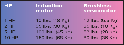
Servomotors weigh less than induction/vector motors.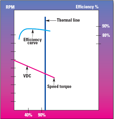
Typical servomotor data with operating and thermal conditions. Servomotors arre designed to be highly efficient.
Current savings by modifying gear ratio or lead screw pitch to attain inertia matching of 5:1 or the ideal 1:1.
:: Design World ::
Filed Under: Machine tools + subtractive manufacturing, Motion control • motor controls, Motors • servo

difference between the all the types of servo motors