Technology giant HP has developed and recently launched Multi Jet Fusion (MJF), an industrial-grade 3D printing technology that quickly and accurately produces functional prototypes and end-use parts for a variety of applications. It’s an all-new additive manufacturing process that brings with it the promise of advancing 3D printing further into the realm of production.
SLS Similarities
If you’re familiar with 3D printing processes like selective laser sintering (SLS), you probably have a solid understanding of MJF. Both SLS and MJF are powder-bed 3D printing technologies that use a heated chamber, parts are stacked throughout the build envelope, and there’s no need for support structures as there is with other 3D printing processes. Where SLS uses a laser to fuse individual powder layers, MJF uses an infrared heating element together with proprietary fusing and detailing agents.
Regardless of the actual manufacturing process, MJF produces fine features and more consistent isotropic material properties when compared to other plastic additive manufacturing processes, and is suitable for complex, low-volume quantities of parts like brackets and clips, mechanical assemblies, component housings, and durable but accurate jigs and fixtures.
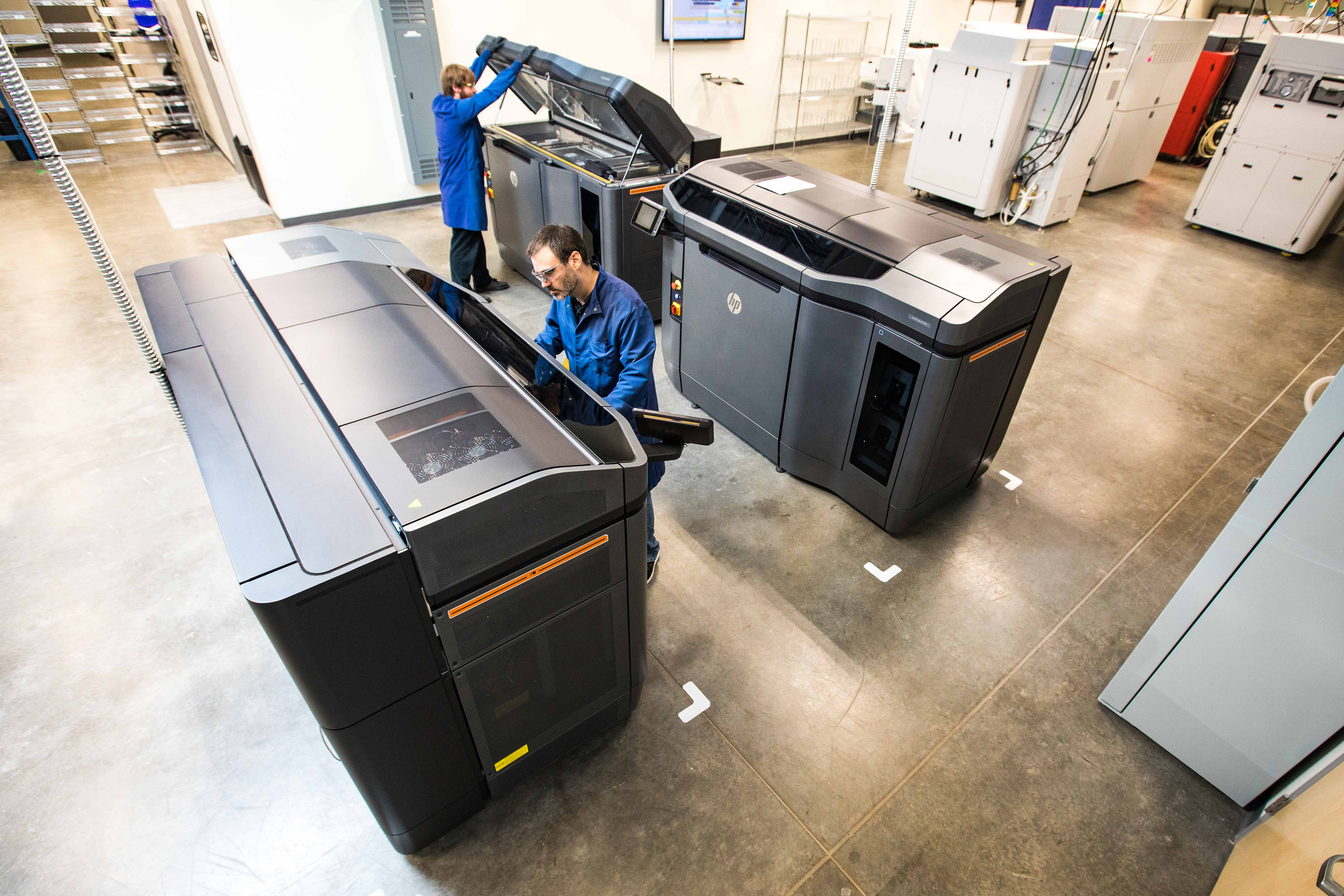
Figure 1: Proto Labs recently added HP’s Multi Jet Fusion technology to its suite of 3D printing processes. MJF produces parts similar to powder-based processes like selective laser sintering.
How MJF is Different?
There are, however, some differences between MJF and SLS that designers and engineers should consider:
- Resolution: MJF prints in layers 0.003 in. (80 microns) thick, and boasts a minimum feature size of 0.020 in. (0.5 mm). This is finer than the 0.030 in. (0.75 mm) produced with SLS, but MJF-produced part details are a bit more variable at this size range, with expected tolerances of +/-0.004 (0.10 mm) over the first inch vs. +/-0.001 (0.025 mm) over the first inch for SLS. Be aware that these tolerances will vary depending on part size and geometry, so pay particular attention on designs that require tight clearance such as housings or multiple mating parts in an assembly.
- Part Size: At 14.9 in. x 11.1 in. x 14.9 in. (380 mm x 284 mm x 380 mm), MJF’s maximum build envelope is a bit smaller than the 19 in. x 19 in. x 17 in. size available with SLS. This means the maximum dimensions of any individual MJF-generated part cannot exceed the aforementioned MJF measurements, although this is plenty big for many 3D-printed parts.
- Materials: Because MJF only prints an unfilled Nylon 12 (PA12), SLS has a slight edge in terms of available materials and colors (for now). However, Nylon 12 provides a breadth of mechanical or thermal properties that are often required of functional parts and in end-use applications. If cosmetics are important, we suggest dying the natural salt-and-pepper gray of MJF parts black; SLS parts can typically be dyed in a variety of colors. A light bead blast for parts is often standard with either MJF or SLS. And both of these secondary operations on MJF and SLS parts are usually handled in-house by suppliers.
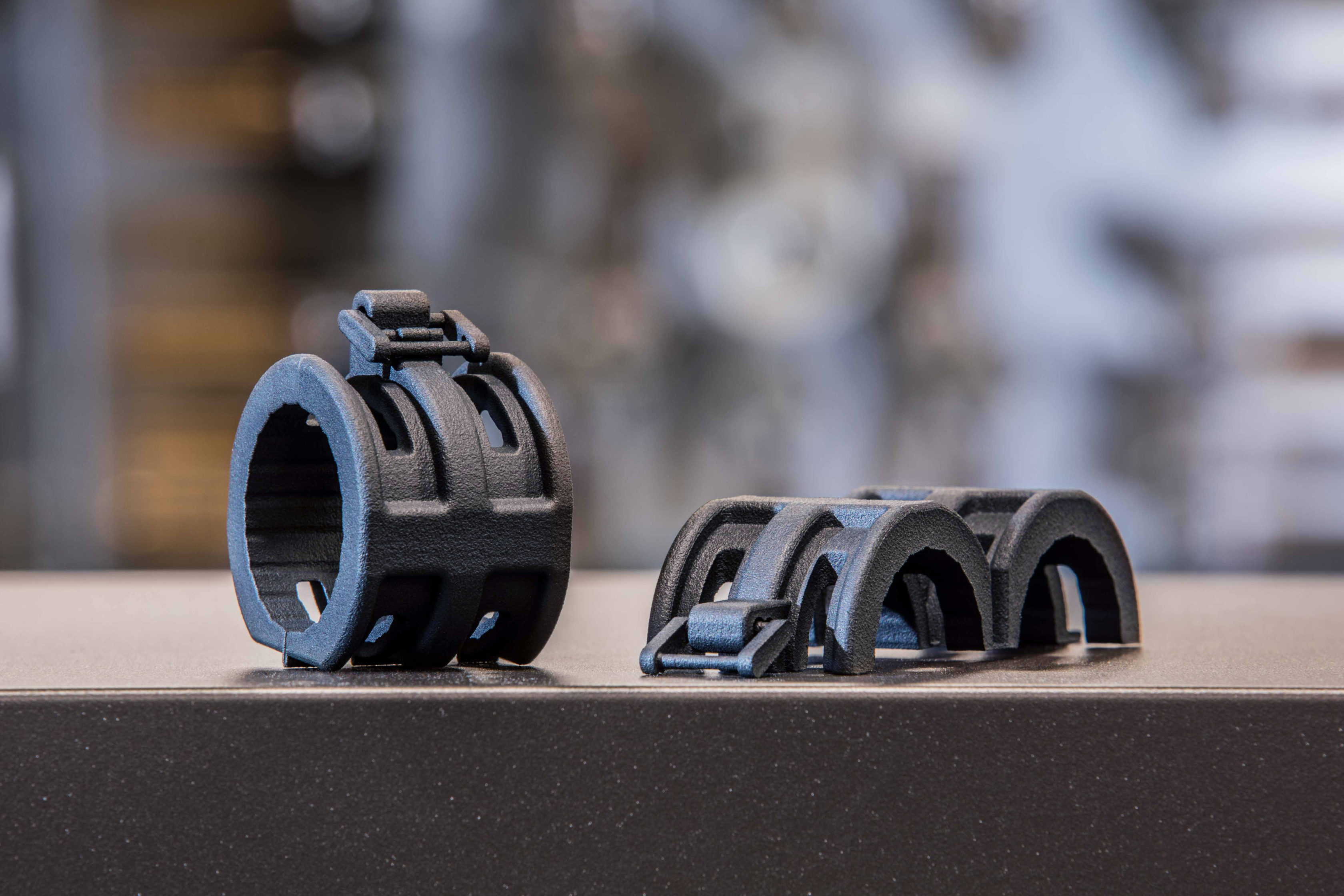
Figure 2: Multi Jet Fusion parts are 3D printed in a natural gray Nylon 12 material, however, parts can be easily dyed jet black (as pictured) for improved cosmetic appearance.
At a Glance: MJF vs. SLS
|
MULTI JET FUSION |
SELECTIVE LASER SINTERING |
|
Finer minimum feature resolution |
Better small feature accuracy (small feature tolerances) |
|
Requires black dye for consistent color
|
More consistent surface color without secondary operations |
|
New process with accelerated build time |
Established process with longer build time |
|
More consistent isotropic mechanical properties in the Z build direction when compared to other additive manufacturing processes |
Broader selection of materials, including filled and specialty materials |
|
Improved surface roughness |
Larger available build envelope
|
Stronger Parts, Faster Process
It’s also important to consider the areas where MJF excels. For starters, MJF builds strong parts, with tensile strength at the upper end (maximum load: XY and Z at 48 MPa/6,960 psi with ASTM D638 method) of what’s possible with SLS. More important, MJF produces more consistent mechanical properties in each direction of the part geometry—far more so than other powder-based printers—a factor that’s especially desirable with multi-faceted, complex designs where strength and reliability is required everywhere throughout the part. So even though MJF is slightly less accurate than SLS on small part features, those features will be more robust.
MJF is also much faster than competing processes. Rather than tracing each individual detail in a build layer, MJF scans the entire surface on each pass at a consistent rate, regardless of how many parts are in that layer (similar to how a laser printer prints each page in a document). Depending on what’s being 3D printed, this provides build speeds several times that of competing technologies, even with larger quantities.
Design Elements to Consider
Many of the design principles applied to SLS and even injection-molded parts are just as relevant with MJF:
- Thin-walled or large, flat surfaces should be reinforced with ribs or gussets, and holes surrounded with raised bosses wherever possible.
- Raised text and cosmetic part features smaller than 0.020 in. (0.5 mm) might not survive secondary post-processing.
- Wall thicknesses from 0.1 to 0.15 in. (2.5 to 3.8 mm) are ideal. Go above 0.15 in. and you’ll have negative dimensional impacts due to different shrink and curling; go below 0.1 in. and your chances of warping increases.
- MJF does a great job with assemblies, living hinges, snap fits, and pin hinges.
- As with any 3D printing process, MJF produces some stair-stepping on oblique angles, however, it’s less noticeable with MJF due to the effects of detailing agents and reduced layer thickness (80 microns). Cosmetic surfaces should be clearly identified on the part drawing or digitally in the product manufacturing information (PMI), so your part supplier can attempt to orient the parts in the build chamber accordingly.
- Heat-stake threaded inserts, taps, and metal bushings can typically be incorporated into MJF parts as a secondary operation for additional strength.
- Although MJF is limited to PA12 nylon at this time, HP is exploring additional materials, including flame-retardant and glass-filled nylon, elastomers, and multiple colors in a single build.
As mentioned at the start of this article, MJF is similar in many ways to other additive manufacturing technologies, offering predictable part quality and possessing design rules that are well understood. What’s different is its unique ability to make accurate parts with consistent isotropic mechanical properties, and in many cases do so more quickly than other 3D printing methods. Together, these attributes have the potential to make MJF an additive game-changer.
Filed Under: Industrial automation, Flanges • supports • mounts • brackets