Understanding USB 3.0 is critical for connector and cable manufacturers to thrive in this new fast-paced world.
Contributed by Ryan Satrom, Signal Integrity Engineer, Omnetics Connector Corp.
USB 3.0 was introduced in 2008. There were early adaptors to this new technology but it took several years before it became ubiquitous as it is today. About a decade after its initial release, USB 3.0 remains a key player in current electronics.
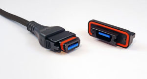 As this technology has progressed, cable assemblies have improved accordingly to meet the requirements of new and challenging applications. While initial USB 3.0 products typically ran well below the 5 Gbps specification, many newer products seek to utilize this maximum data rate, sometimes with cables up to 5 m in length. The combination of higher data rates and increased cable lengths requires maximum performance from the cable assembly.
The mechanical requirements are also being challenged. Though USB was designed for the commercial environment, new industries such as military and aerospace are seeking to implement this technology. This requires a rugged connector design that can be lightweight, protect from dust and water ingress (IP67/IP68), and successfully operate under shock and vibration stresses, while providing 1,000-plus mate/de-mate cycles.
These challenges require a meticulously designed connector and cable. In this article, we will provide an introduction to USB 3.0 and then describe some of the technical challenges that connector and cable manufacturers must consider in order to thrive in this new world.
Specifications and connector types
Within the span of one year, the USB organization released two different specifications: USB 3.1 and USB Type C. “USB 3.1” and “Type C” are sometimes used interchangeably, but the reality is these are two separate documents: USB 3.1 primarily defines the electrical requirements for USB 3.1 functions and signals; while the Type C specification primarily defines the connector requirements for the new Type C footprint.
The confusion arises because there exist connectors that are both USB 3.1 and Type C. However, clarification is needed because there are also Type A and Type B connectors for USB 3.1, and there are USB 2.0 and USB 3.0 connectors that use the Type C footprint.
USB 3.0 versus USB 3.1
Added confusion arose with the USB 3.1 specification when the descriptor USB 3.0 was obsoleted: What is often described as USB 3.0 is now officially called USB 3.1 Gen 1, and what is typically understood as USB 3.1 is actually USB 3.1 Gen 2. In other words, USB 3.0 no longer exists. This obsolescence, however, has not stopped most of the industry from continuing to use the USB 3.0 descriptor. For simplicity, this article will use USB 3.0 to refer to USB 3.1 Gen 1.
The progression of USB 3.0 technology
In the early stages of USB 3.0, many cable and connector manufacturers were unable to meet the requirements of USB 3.0. The impedance requirement of 90Ω ± 15Ω at the connector and the skew recommendation of 15 ps/m were seldom met. When Omnetics ran an informal test of a dozen off-the-shelf USB cable assemblies in 2014, only one of the assemblies met the USB 3.0 specification. However, because the products were not pushing the limits of the technology, it was rare to hear of any performance issues in the field. The bottom line was, in the early stages of USB 3.0, even cable assemblies that did not meet the USB specification were functioning properly in the field. Consequently, there was little motivation to improve their performance.
As the technology has matured, new hardware has been introduced that utilizes the 5 Gbps data rate, forcing cable and connector manufacturers to meet the full requirements.
Meeting the connector requirements
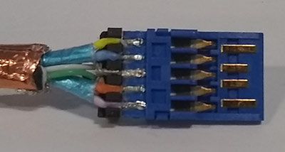
Figure 1. USB 3.0 connector terminations. The image above shows a good termination. The foil shield is held tight against the wires until it is very close to the blue insulator. Conversely, the foil shield on the bottom connector is cut back about 1/3-in
The primary specification that the connector impacts is the differential impedance. Controlling the impedance requires a constant cross-section for the critical signals. This is easy to achieve in a cable, as the cross-section remains mostly constant throughout the entire cable. It is much more difficult through the connector because the cross-section is continually changing: The signals travel from wires, to solder pads, then to connector pins. Each of these regions has a different cross-section, and thus a different impedance. It is for this reason that the specification allows a larger impedance range through a connector than through a cable (90Ω ± 15Ω for the connector versus 90Ω ± 7Ω for the cable).
The main area which causes the impedance to fail specification is the signal wires near the connector pads. In this area, the foil around the twisted pairs is removed in order to connect the wires to the solder pads. Since the foil is used to control the impedance of the wires, its removal causes the impedance to spike. For this reason, it is critical to minimize the length of foil shield that is removed.
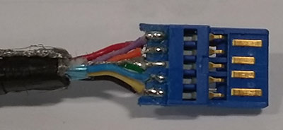 In Figure 1, the top connector shows a good termination. The foil shield is held tight against the wires until it is very close to the blue insulator. Conversely, the foil shield on the bottom connector is cut back about 1/3-in. The difference between these two connectors is likely the difference between passing and failing the impedance specification.
Meeting the cable requirements
Successfully designing a USB 3.0 cable must include proper consideration for the impedance and intra-pair skew of the critical pairs.
Matching the impedance requires controlling the thickness of the wire insulation, tightly twisting the pairs together, and including a shield around each pair. Controlling the wire insulation thickness and twisting the pairs alone will provide a relatively good impedance match, and the foil is used to maintain a tight impedance tolerance throughout the cable.
Minimizing intra-pair skew — the time difference between electrical signals within a pair — requires a tightly controlled design. If the surrounding environment is not identical for the two lines within a pair, skew is introduced. This can be a result of asymmetries in the wire extrusion, pairs that are too loosely twisted, or slight variations within the extruded plastic. In short, minimizing skew requires a good cable design and a tightly monitored manufacturing process.
It is also important to consider cable length. To meet specification, the length of the assembly must be kept to a maximum between 2 and 3 m. Cables that are longer than this will fail the loss requirement. For most applications, this means the cable will fail the application. However, not all applications will fail. Omnetics works with customers that can successfully pass signals through cables with a length of five meters.
Ruggedizing the design
Electrical requirements are not the only parameters that are being challenged. Mechanically, USB 3.0 is being pushed into arenas well beyond commercial. Many military applications are seeking solutions, typically requiring a flexible and abrasion resistant cable jacket combined with a dust/water-proof connector solution with high mate/de-mate cycles. Aerospace, another area that is expressing interest, typically looks for stringent shock/vibration testing and low outgassing requirements.
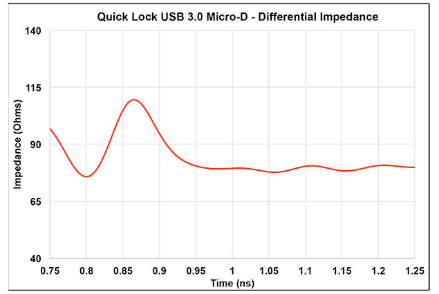
Figure 2. Differential impedance of Omnetics Quick Lock USB 3.0 connector
Connectors must be designed to be small and lightweight, with an IP68 seal, and up to 2,000 mating/de-mating cycles. Latches can also be used as a locking mechanism without compromising the shock and vibration requirements called out in many military specifications.
A ruggedized cable requires replacing jacket material — typically PVC for most USB 3.0 applications — with various formulations of either polyurethane or Teflon.
Polyurethane provides excellent flexibility and abrasion resistance, so it is preferred for most military applications. Teflon is preferred in aerospace because it provides low outgassing and high-temperature performance.
Putting it all together
One solution on the market that is meeting these requirements is the Omnetics Quick Lock USB 3.0. Advanced techniques are used to maintain tight control over the manufacturing process. These new techniques enable the pair shields to be kept tight to the wires all the way up to the solder pads, which is necessary to ensure a good impedance through the connector (See Figure 2).
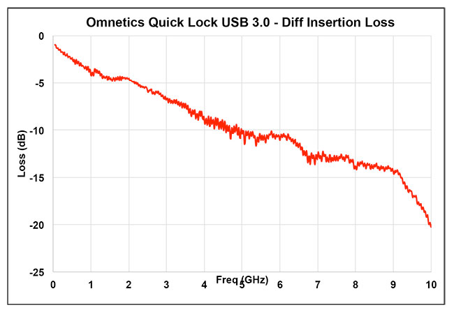
Figure 3. Differential insertion loss for 2-meter Omnetics Quick Lock USB 3.0 cnnector assembly
The proper cable was determined through a lengthy process that involved countless cable iterations. As mentioned earlier, finding a cable that provides less than 15 ps/m of intra-pair skew is not trivial. Our final cable yielded an intra-pair skew of around 12 ps/m.
High-performance insulation material was used to maximize the insertion loss. Figure 3 shows the insertion loss of a 2-m assembly, which meets the loss requirements for USB 3.0.
The design includes a housing that ensures the highest levels of reliability while giving users the ability to mate and de-mate in a rapid fashion without any tools. Once mated, this ruggedized high-speed connection is secure and waterproof to IP68 standards, and utilizes a significantly smaller footprint than other ruggedized USB connectors that are packaged in the MIL-DTL-38999 circular standard. Assemblies are also available with commercial USB assemblies (Type A, Type B, Type B Micro) terminated to the other side.
Conclusion
In this new era of connector design, mechanical and electrical requirements must be considered equally. Finding a proper solution also requires the connector and cable to both be considered equally. By applying the concepts discussed in this article, a solution that meets the needs of a wide variety of customers is possible. DW
Omnetics
omnetics.com
Filed Under: Cables + cable management, Connectors (electrical) • crimp technologies

Tell Us What You Think!