The controller area network (CAN) protocol is a proven, highly reliable communication system for harsh industrial and automotive environments. Using a CAN two-wire bus multi-master/multi-drop topology makes it easy to add additional functionality to a system while significantly reducing the number of wires associated with wire intensive point-to-point topologies.
The space community is well aware of the CAN protocol’s many advantages and the need for it to replace traditional satellite bus architectures. The European Space Agency (ESA) has led the development effort to put the hardware, firmware and software in place to implement CAN for spacecraft communications and control systems.
This article examines the use of CAN bus in space flight applications. We’ll discuss the basics of the CAN serial communications protocol, advantages of implementing CAN for satellite communications, and the stringent requirements for radiation tolerant CAN transceivers.
CAN Protocol Basics
Figure 1 shows a block diagram of a typical CAN bus network. It consists of two differential signal lines designated as CANH and CANL. Electronic control unit (ECU) devices connect to the differential data lines and communicate with each other over the differential bus. 120Ω termination resistors are used at the end of the bus to suppress electrical signal reflections.
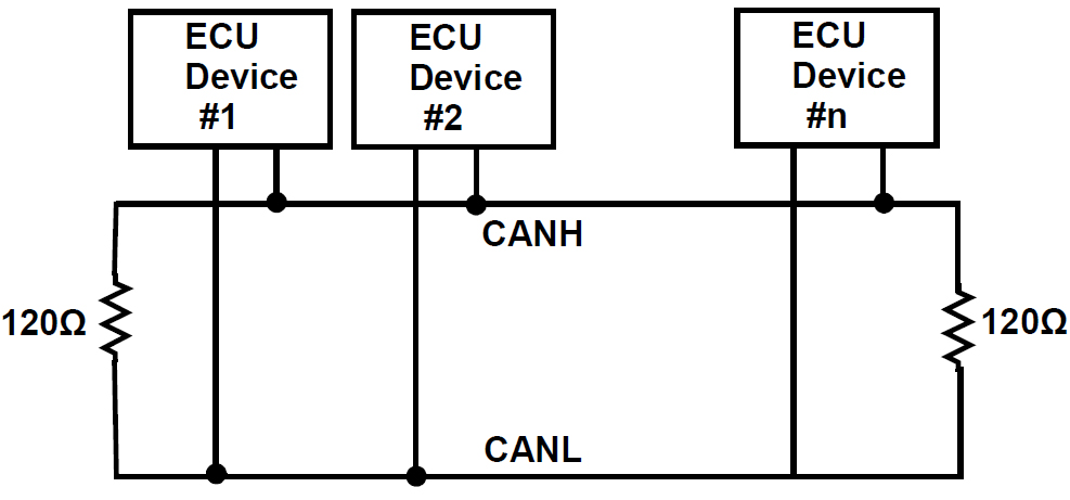
Figure 1. Block Diagram of a CAN Bus Network
A block diagram showing the ECU’s basic components is shown in Figure 2. The ECU consists of a CAN transceiver, CAN controller/embedded µP, clock source, analog-to-digital converter (ADC), digital-to-analog converter (DAC), transducer, signal conditioning circuitry, sensor, and actuator.
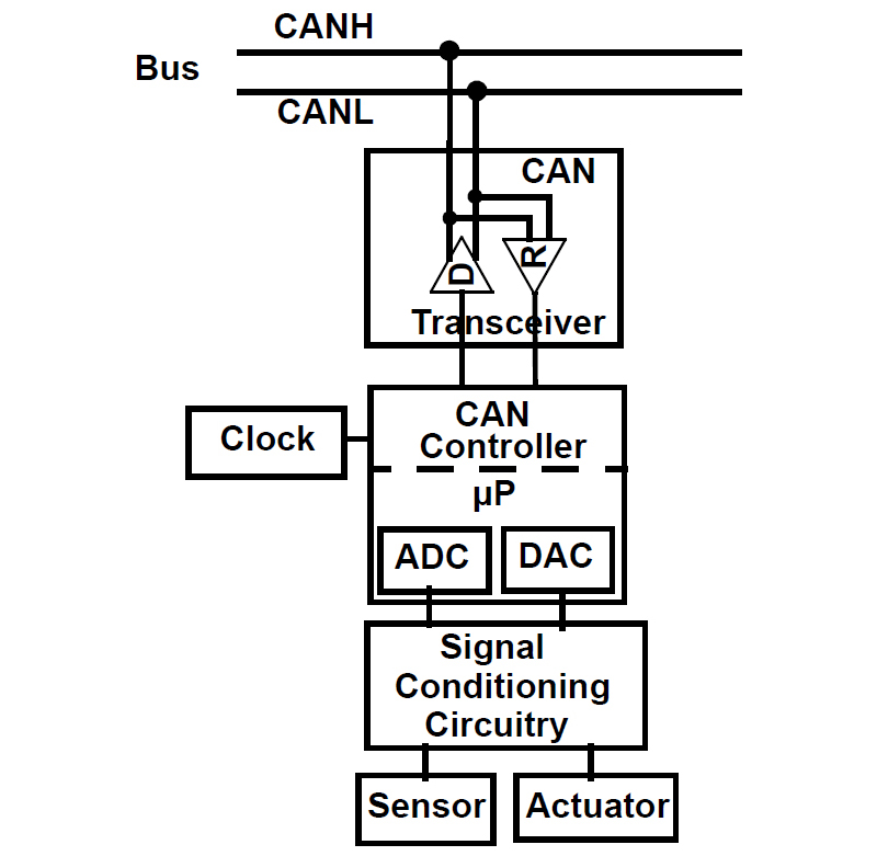
Figure 2. Block Diagram of an ECU Device
To communicate on the bus, every ECU must have a CAN controller and a CAN transceiver that conforms to the ISO 11898-1/-2:2003 standards. ECUs are smart devices and each ECU has the ability to transmit a CAN data packet onto the bus and receive broadcasted data packets.
Each ECU’s CAN controller filters the received data packet coming from the CAN transceiver to determine if it should take any action. The CAN controller also executes the data transmission. The CAN controller puts the digital data into the proper CAN format and when it determines the bus is idle, it initiates the serial data stream transmission to the input of the CAN transceiver. The CAN transceiver responds to the serial data stream at its input by driving the signal lines with the proper differential signals, representing either a logic 0 (dominant bit) or a logic 1 (recessive bit).
The CAN controller conforms to the data layer specifications in ISO 11898-1, while the CAN transceiver conforms to the electrical specifications in ISO 11898-1/-2. It is IS0 11898-2 that states the electrical specifications and signal requirements for driving the bus with data rates up to 1Mbps.
CAN Advantages in Space Applications
Employing a CAN bus communications network in satellites enables much lower power consumption and reduces the amount of wiring and connectors vs. the conventional MIL-STD-1553 and RS-485 point-to-point interface solutions. Figure 3 shows the comparison between a conventional topology vs. the CAN two-wire broadcast topology. With CAN, several nodes are attached to a single bus. This significantly reduces system and cable costs. According to ESA, a satellite can reduce weight and mass by 10-18 percent, which adds several million dollars of functionality, while increasing reliability, observability, and controllability.
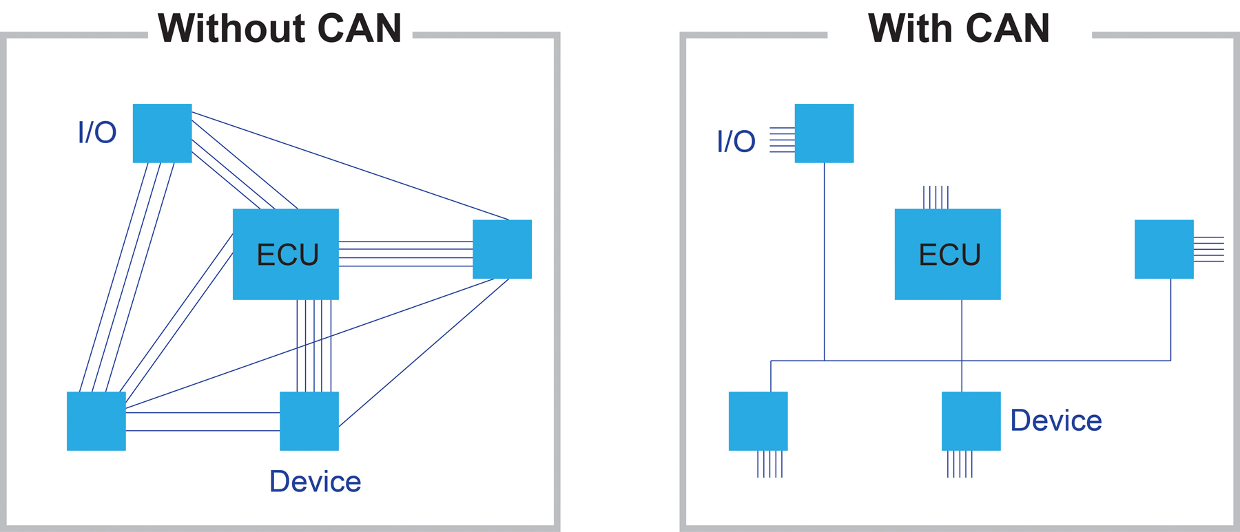
Figure 3. CAN Networks Significantly Reduce Wiring
Requirements of a Radiation Tolerant CAN Transceiver
Before a CAN transceiver is used in space applications, it must meet the key electrical specification of the ISO 11898–2 standard. In addition, it must be able to survive the radiation environment of space, and support system redundancy and fault detection. Space radiation effects on electronic devices can lead to various types of problems ranging from operational malfunctions to physical damage.
CMOS technology is preferred for space applications because of its high noise margins and low static power requirements. However, CMOS is susceptive to total ionizing dose (TID) and single-event effects (SEE). Both of these phenomena can have adverse effects on semiconductors, if not properly handled.
The total dose radiation exposure is measured in rads. The term rad (radiation-absorbed dose) quantifies the total radiation exposure of a material. One rad(Si) is equal to 10×10-6 W of energy absorbed per gram of silicon. The total dose radiation threshold of a device is the minimum level of rad(Si) that will cause device failure. Typical commercial CMOS technology devices can survive around 5krads before physical damage occurs. However, SEE are significantly more hazardous to the satellite and can result in single event upset (SEU), single event transient (SET) or single event latch-up (SEL).
SEU effects are internal device memory bit changes (0 becomes 1 and vice versa) that can cause erroneous instruction execution, and SET is a transient voltage pulse that can cause erroneous data transmission over a bus. SEU and SET effects are considered soft-errors and do not physically damage the devices. In contrast, SEL effect is a hard-error, which leads to a high current-flow through the device. If not remedied quickly, latch-up can cause permanent damage.
TID testing on the ISL7202xSEH family of CAN transceivers was done to 75krad(Si) at 0.01rad(Si)/s under biased and grounded conditions and were followed by a biased anneal at 100oC for 168 hours as outlined in MIL-STD-883 Test Method 1019. These radiation tolerant devices have a lose dose rate guarantee of 75krads.
Reliability is an essential requirement in space applications and single point failures must be avoided. To avoid system failure, an ECU node will use two ISL7202xSEH CAN transceivers in parallel. One transceiver will be active while the other transceiver is a “cold spare” powered down. The cold spare transceiver is used if the active transceiver malfunctions.
Conclusion
With the arrival of QML-V qualified, radiation tolerant CAN bus transceivers, system engineers can implement a CAN bus network for spacecraft onboard communications and controls, and replace the more complex wiring architectures, such as MIL-STD-1553. Reducing the number of wires and weight along with lower power consumption will result in major cost savings for spacecraft manufacturers.
Filed Under: Aerospace + defense