Design World

  • Home
  • Technologies
    • 3D CAD
    • Electronics • electrical
    • Fastening & Joining
    • Factory automation
    • Linear Motion
    • Motion Control
    • Test & Measurement
    • Sensors
    • Fluid power
  • Learn
    • Ebooks / Tech Tips
    • Engineering Week
    • Future of Design Engineering
    • MC² Motion Control Classrooms
    • Podcasts
    • Videos
    • Webinars
  • LEAP AWARDS
  • Leadership
    • 2022 Voting
    • 2021 Winners
  • Design Guide Library
  • Resources
    • 3D Cad Models
      • PARTsolutions
      • TraceParts
    • Digital Issues
      • Design World
      • EE World
    • Women in Engineering
  • Supplier Listings

InSight Mars Lander Takes Its First Selfie

By NASA Jet Propulsion Laboratory | December 12, 2018

Share

NASA’s InSight lander isn’t camera-shy. The spacecraft used a camera on its robotic arm to take its first selfie—a mosaic made up of 11 images. This is the same imaging process used by NASA’s Curiosity rover mission, in which many overlapping pictures are taken and later stitched together. Visible in the selfie are the lander’s solar panel and its entire deck, including its science instruments.

Mission team members have also received their first complete look at InSight’s “workspace—the approximately 14-by-7-foot (4-by-2-meter) crescent of terrain directly in front of the spacecraft. This image is also a mosaic composed of 52 individual photos.

In the coming weeks, scientists and engineers will go through the painstaking process of deciding where in this workspace the spacecraft’s instruments should be placed. They will then command InSight’s robotic arm to carefully set the seismometer (called the Seismic Experiment for Interior Structure, or SEIS) and heat-flow probe (known as the Heat Flow and Physical Properties Package, or HP3) in the chosen locations. Both work best on level ground, and engineers want to avoid setting them on rocks larger than about a half-inch (1.3 cm).

“The near-absence of rocks, hills and holes means it’ll be extremely safe for our instruments,” said InSight’s Principal Investigator Bruce Banerdt of NASA’s Jet Propulsion Laboratory in Pasadena, California. “This might seem like a pretty plain piece of ground if it weren’t on Mars, but we’re glad to see that.”

InSight’s landing team deliberately chose a landing region in Elysium Planitia that is relatively free of rocks. Even so, the landing spot turned out even better than they hoped. The spacecraft sits in what appears to be a nearly rock-free “hollow—a depression created by a meteor impact that later filled with sand. That should make it easier for one of InSight’s instruments, the heat-flow probe, to bore down to its goal of 16 feet (5 meters) below the surface.

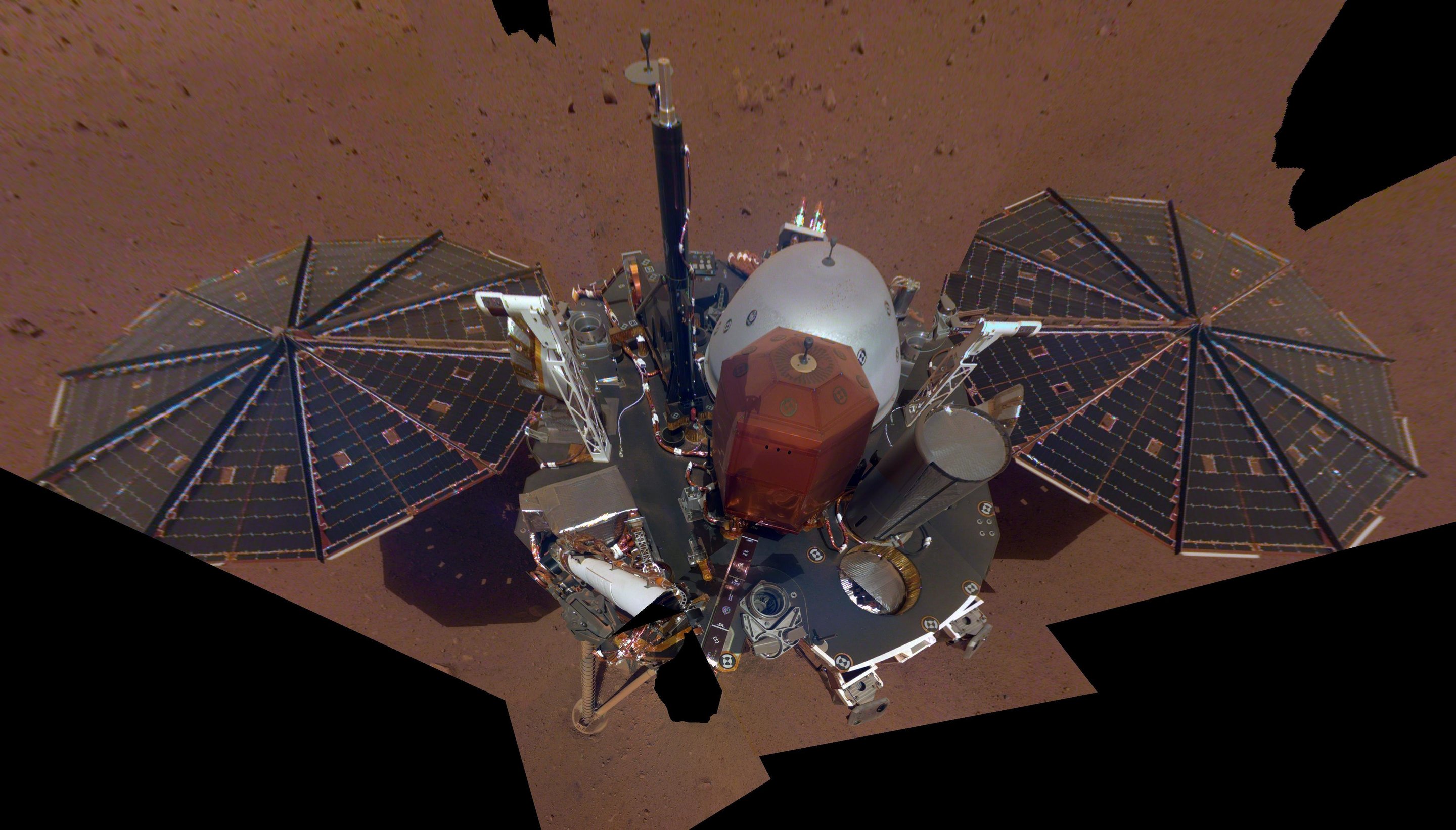
This is NASA InSight’s first full selfie on Mars. It displays the lander’s solar panels and deck. On top of the deck are its science instruments, weather sensor booms and UHF antenna. The selfie was taken on Dec. 6, 2018 (Sol 10). The selfie is made up of 11 images which were taken by its Instrument Deployment Camera, located on the elbow of its robotic arm. Those images are then stitched together into a mosaic. Credit: NASA/JPL-Caltech


Filed Under: Aerospace + defense


Related Articles Read More >

Mars helicopter receives Collier Trophy
Flexible rotary shafts to power Delta Airlines’ engines powering their first Airbus A321neo aircraft
Ontic acquires Servotek and Westcon product lines from Marsh Bellofram
Flexible rotary shafts support thrust reverser on 150 LEAP 1-A turbofan engines

DESIGN GUIDE LIBRARY

“motion

Enews Sign Up

Motion Control Classroom

Design World Digital Edition

cover

Browse the most current issue of Design World and back issues in an easy to use high quality format. Clip, share and download with the leading design engineering magazine today.

EDABoard the Forum for Electronics

Top global problem solving EE forum covering Microcontrollers, DSP, Networking, Analog and Digital Design, RF, Power Electronics, PCB Routing and much more

EDABoard: Forum for electronics

Sponsored Content

  • Pushing performance: Adding functionality to terminal blocks
  • Get to Know Würth Industrial Division
  • Renishaw next-generation FORTiS™ enclosed linear encoders offer enhanced metrology and reliability for machine tools
  • WAGO’s smartDESIGNER Online Provides Seamless Progression for Projects
  • Epoxy Certified for UL 1203 Standard
  • The Importance of Industrial Cable Resistance to Chemicals and Oils

Design World Podcasts

June 12, 2022
How to avoid over engineering a part
See More >
Engineering Exchange

The Engineering Exchange is a global educational networking community for engineers.

Connect, share, and learn today »

Design World
  • Advertising
  • About us
  • Contact
  • Manage your Design World Subscription
  • Subscribe
  • Design World Digital Network
  • Engineering White Papers
  • LEAP AWARDS

Copyright © 2022 WTWH Media LLC. All Rights Reserved. The material on this site may not be reproduced, distributed, transmitted, cached or otherwise used, except with the prior written permission of WTWH Media
Privacy Policy | Advertising | About Us

Search Design World

  • Home
  • Technologies
    • 3D CAD
    • Electronics • electrical
    • Fastening & Joining
    • Factory automation
    • Linear Motion
    • Motion Control
    • Test & Measurement
    • Sensors
    • Fluid power
  • Learn
    • Ebooks / Tech Tips
    • Engineering Week
    • Future of Design Engineering
    • MC² Motion Control Classrooms
    • Podcasts
    • Videos
    • Webinars
  • LEAP AWARDS
  • Leadership
    • 2022 Voting
    • 2021 Winners
  • Design Guide Library
  • Resources
    • 3D Cad Models
      • PARTsolutions
      • TraceParts
    • Digital Issues
      • Design World
      • EE World
    • Women in Engineering
  • Supplier Listings