Rapidly evolving production processes have driven the need for motion control systems that provide higher accuracy, speed, resolution and repeatability. In response, motion control manufacturers have unleashed a number of mechanisms, position and force feedback technologies, and electromechanical actuation technologies. Together, these innovations are enabling new actuation and feedback systems for mission-critical deployment in automation, laser processing, optical inspection, photonics alignment, semiconductor metrology, and medical device and micro-machining applications.
In a similar vein, these motion control technology advancements are also driving the laboratory research market, where swiftly advancing scientific endeavors necessitate ever finer and faster motion control. Innovative electromechanical actuation and feedback technologies are driving the development of very high-resolution microscopies, single-molecule biophysics investigations, and the latest materials and photonics.
Engineers have access to a wide range of precision motorized positioning systems that provide very few limitations on travel, precision, repeatability and speed. Some of the more prominent types of motorized precision positioning systems are described below.
figure 1. a voice-coil linear motor actuator has integrated high resolution position and force sensors, for automation applications. Image credit: Physik Instrumente
Motorized linear actuators are high-precision positioning devices that create motion in one degree of freedom. They typically do not include a guiding system for the payload. While electrically-driven actuators draw the most interest, micrometer-driven actuators are also common, along with screw-driven, pneumatic and hydraulic variants for lower-precision applications.
By attaching a linear DC motor (which can be thought of as a rotary DC motor sliced lengthwise and laid flat) to linear guidance and an output shaft, direct linear actuation of very high speeds can be achieved. Linear DC motors can have a multitude of north/south magnetic pairs, depending on how much travel is needed. These serve the role of the stator in a rotary motor. Gliding along them to generate force is a three-phase coil assembly. The phases are commutated electronically to generate smooth motion in the desired direction, ensuring long life.
A related type of linear actuator is driven by a voice coil motor – a nested pair of cylindrical electromagnetic coils which attract or repel each other along their mutual axis. These provide travels on the order of 25 mm and provide high speeds and accelerations for small loads. Such mechanisms are very long lived. Voice coil actuators (see Figure 1) can offer impressive step/settle times owing to their high responsiveness, and their direct actuation of the motion shaft in its low-friction bearings offers exquisite force control, as well, when an optional tip-force sensor is incorporated.
Piezoelectric actuators represent a large segment of linear actuators. They can achieve extremely fine positioning resolution and come in various types:
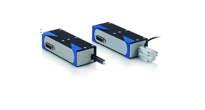
Figure 2. Walking piezomotors have four or more ceramic fingers that actuate in a stepping sequence to drive a work piece in the desired direction.
Piezoelectric actuators represent a large segment of linear actuators. They can achieve extremely fine positioning resolution and come in various types:
Piezo Stack Actuators are layered structures of specialized ceramic interleaved with metallic electrodes. The piezoceramic can expand in a controllable manner with the application of an electrical field. These actuators provide short travel ranges (about 1 percent of their length), sub-nanometer precisions, high forces and sub-millisecond response. These are the mainstay of today’s advanced nanotech applications, both in laboratory research and in industrial applications such as semiconductor manufacturing and genomic sequencing. Piezo stack actuators are inherently non-magnetic, solid state and vacuum-friendly, with no wear processes.
Ultrasonic Piezomotors are monolithic piezoceramic structures that are stimulated at their resonant frequency, typically above 100 kHz, causing them to flutter on a submicron scale. A friction tip formed or bonded at a resonant node conveys this fluttering oscillation to a work piece that rides in bearings. The work piece thereby experiences a force that drives it one direction or the other. These motors can achieve many millimeters of travel and extraordinary speeds in a very small package.
Inertia Drives are another type of piezomotor that uses tiny piezoceramic elements are actuated in a saw tooth pattern, driving a shaft or other actuated element via a friction coupling. The sloped portion of the saw tooth actuation is what provides the motion; the rapid retraction breaks the stiction of the coupling and the actuated element does not retract with the piezo ceramic element. A well-design inertia drive can achieve silent, virtually stepless operation and long travels, together with nanoscale precision,, and self-locking for high stability when stationary.
Walking Piezomotors use four or more piezoceramic fingers which actuate in a stepping sequence to drive a workpiece in a desired direction (see Figure 2). Between steps, sub-nanoscale actuation can be achieved. High power-off holding forces and essentially unlimited travel characterize these designs. The usual non-magnetic and vacuum-friendly attributes apply. These have proven to be enablers in sensitive optical positioning applications where carefully established positions must be maintained with nanometer stability..
Electromechanical Actuators
Electromechanical Actuators represent another category of actuators. These are typically based on linear shafts driven by rotational electromagnetic motors via lead nuts or ball nuts. Rotary motion of the motor is converted to linear displacement. The actuators have a generally cylindrical format. Small versions are used to replace micrometers or precision screws, conferring automated actuation.
Electromechanical actuators typically employ either stepper motors or DC servomotors. Stepper motors actuate a toothed rotor within a toothed, surrounding stator. The most common type – the permanent magnet stepper motor – uses a rotor composed of a magnetized material. By configuring the magnetic windings of the stator so that groups of its teeth can be specifically magnetized, the rotor rotates in steps by partially energizing the windings. Consequently, a driving mode that yields mini- or microsteps can be implemented, multiplying the stepping resolution of the motor.
DC servomotors employ a magnetized rotor within a magnetized stator, both of which have a north and a south pole. The poles of each are attracted or repelled to each other, causing rotation to an equilibrium orientation.. By varying the magnetization of the rotor or stator, or both electromagnetically, such as by switching their polarities using a brushed or electronic commutation approach, the motor can be made to spin freely and, with the addition of a position feedback encoder, provide precise positioning with exceptional responsiveness. Brushless DC motors, with electronic commutation rather than brush commutation, provide enhanced lifetime, especially in high-dynamic applications.
In both cases, the motors can be operated open- or closed-loop.. A stepper motor can be actuated through any specified number of steps in either direction and offers a high probability of achieving them, though certainty can only be achieved by adding a position encoder. Rotary encoders track the position of the rotating motor; linear encoders directly encode the output position of the driven linear shaft, eliminating backlash and other errors that might otherwise accumulate in the drivetrain where a rotary encoder cannot observe them.
A linear or translation stage builds on the principles of a linear actuator, but adds a platform or workpiece for attaching an application load, or for stacking additional stages to form a multi-axis configuration. The stage’s workpiece is a precision component with a linear bearing for guidance.
A linear translation stage restricts the application load to a linear single degree of freedom. An ideal linear stage completely restricts three axes of rotation and two axes of translation, thus allowing for motion on only one translational axis. In reality, there is no perfect guiding system, and every linear motion will also bring about rotary/tilt errors (angular deviation) and motion components in two unwanted linear degrees of freedom (runout). Motorized linear stages comprise a platform and a base, joined by some form of guide or linear bearing in such a way that the platform is restricted to linear motion with respect to the base. The position of the moving platform relative to the fixed base is typically controlled by a linear actuator of some form.
As drive technology options have expanded, linear stages that incorporate the latest drive technologies have been introduced. These yield advantages of importance to specific applications, such as non-magnetic actuation or package-size benefits. For example, recent developments in microscopy stages provides both higher and lower speed capabilities than typical stepper-motor microscopy stages, and they incorporate a linear encoder for 100 nm-scale bi-directional repeatabilities, all without the bulky overhanging stepper-motor/leadscrew assembly that projects from the side of each axis of conventional microscopy stages.
For motions and positioning in multiple axes, individual positioning stages can be combined or parallel-kinematic hexapods with up to 6 degrees of freedom of motion can be used.
Smaller is In
The need for miniaturization in the semiconductor and medical device industry also drives the requirements for smaller motion systems. Smaller also means lower mass and the potential for higher acceleration and throughput, especially when combined with today’s most advanced actuation technologies.
Linear positioning stages with piezomotors are a new generation of piezoceramic linear motors that enable construction of matchbox-to-thumbnail-sized linear stages with nanometer resolution and millisecond step and settle times. The direct drive avoids mechanical components such as gears and leadscrews, making for reliable and high-resolution drives down to a few nanometers. Depending on the drive principle, high velocity, high forces and/or high resolution are achieved.
Long Travel for Industrial Applications
On the other hand, some industrial automation processes such as flat panel testing, and laser processing, require very long travels past one meter with high speed and low runout errors. Air bearing stages with linear motors have emerged as the standard for these applications.
Air Bearing Linear Stages with Planar XY Stages replace mechanical bearings with a frictionless air film and maximize throughput while providing high precision, especially for multi-axis motion. Planar designs (see Figure 3) use one reference base plane on which magnetically or vacuum preloaded pucks are floating for both the X and Y axes. H-bridge, three-motor designs provide the highest precision, and can be improved with active yaw control when equipped with three linear encoders and advanced motion controllers. The benefit is improved orthogonality and straightness. Air bearing stages are usually driven by magnetic linear or torque motors that provide smooth motion without negative cogging effects.
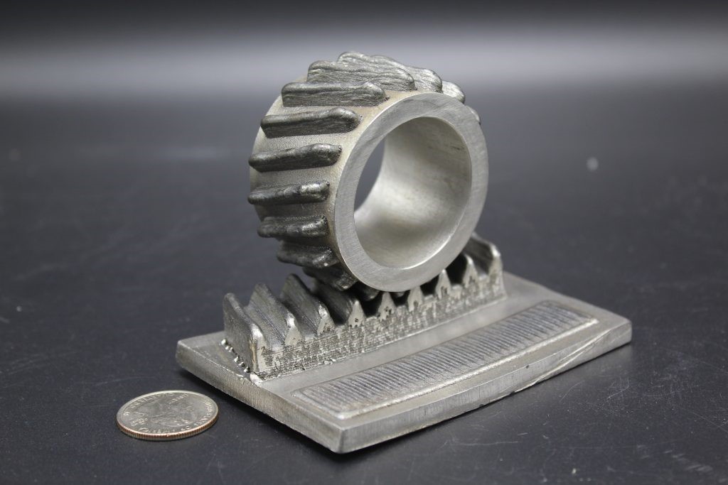
Figure 3. Air Bearing Linear Stages with Planar XY stages use one reference base plane on which magnetically or vacuum preloaded pucks are floating for both the X and Y axes.
High-Speed Stages with Linear/Torque Motor Direct Drive: Linear and torque motors can also be combined with mechanical bearings. This combination is often used in industrial applications when the smoothness and straightness/flatness of motion is not quite as critical as with air bearings. Linear motors combine reliability, precision and speed. Their high dynamics ensures high throughput of automated tasks in testing systems, for example, in the semiconductor industry. They also increase efficiency, for example, in electronics production/assembly lines or laser processing.
High-Resolution Linear Encoder Feedback: Unlike motion systems that are run by rotary stepper and servomotors and lower precision rotary encoders, linear motors require linear positional feedback systems (see Fig. 4). A linear encoder is a digital position transducer that directly measures linear motion where it occurs, as opposed to a rotary encoder mounted at the end of a drive train. The encoder reads the actual position as close to the point of interest as possible, and therefore, the resulting accuracy and repeatability of the payload is higher.
Linear encoders commonly achieve resolution in the sub-nanometer range is common, with accuracy typically limited to 1 micron per 100 mm. However, this can be improved significantly with modern controllers if calibrated and compensated for with look-up tables or polynomial error correction.
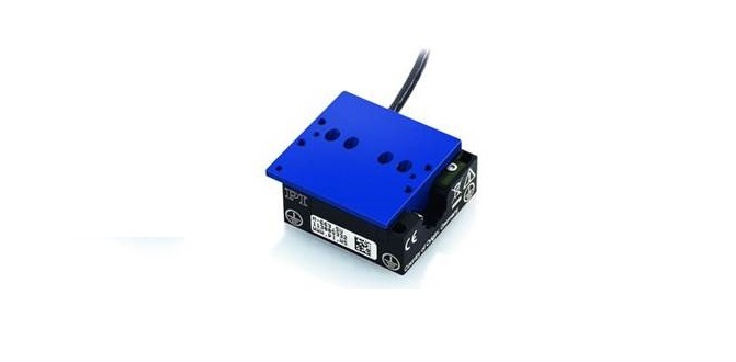
Figure 4. Miniature linear positioning stage with high-speed ultrasonic ceramic linear motor and linear encoder feedback.
Rotation stages comprise a platform that rotates relative to a base. The platform and base are joined by some form of bearing which restricts motion of the platform to rotation about a single axis.
Various motors and drive principles can be employed, from stepper-motor driven worm gear designs to direct-drive closed-loop torque motors. Low-profile piezomotor stages provide self-locking capabilities with zero jitter and drift and requiring no holding current at rest.
Precision motorized rotation stages are used in applications such as fiber-optical alignment, semiconductor inspection, biomedical applications and X-ray crystallography.
Air-Bearing Rotation Stages use a thin film of pressurized air to provide an exceedingly low friction load-bearing interface between surfaces. The two surfaces do not touch. As they are contact-free, air bearings avoid the traditional bearing-related problems of friction, wear, particulates and lubricant handling, and offer distinct advantages in precision positioning and in high-speed applications, where eliminating backlash and static friction are critical.
Typically used for the highest precision and smoothness of motion/velocity, air-bearing rotation stages deliver ultra-low runout and wobble, as well as extremely high resolution and repeatability. Pitch, yaw, roll on the order of 1 arc second are feasible. The absence of friction eliminates backlash and gives the air bearing stage high repeatability.
Goniometers are instruments that either measure an angle or allows an object to be rotated to a precise angular position. They are often used in crystallography and in X-ray diffraction to rotate the samples, and are also useful in (fiber) optic alignment applications.
A positioning goniometer or goniometric stage is a device used to rotate an object precisely about a fixed axis in space. It is similar to a linear stage, however, rather than moving linearly with respect to its base the stage platform rotates partially about a fixed axis above the mounting surface of the platform. Positioning goniometers typically use a worm drive with a partial worm wheel fixed to the underside of the stage platform meshing with a worm in the base.
Hexapods
In order to achieve precision at the micron and sub-micron level in multi-axis motion applications, hexapod parallel positioners have become popular. Hexapods, six-legged parallel-kinematic mechanism (PKM) motion systems, effectively reduce the footprint, and moving mass of a traditional serial kinematic stacked-stage positioning system while increasing stiffness and responsiveness. This, together with the arbitrary, user-defined center of rotation and a large clear aperture, suit hexapods for -critical applications including laser processing, photonics alignment and micro-machining in medical devices and other applications.
Hexapods, in their most common form consisting of two platforms, a fixed-base platform and a second movable platform, which are connected and supported by six independent legs (struts or links) that expand and contract in parallel. A similar 6-axis design, called SpaceFab (see Figure 5), is based on a top platform connected to three XY linear stages with three passive struts. It provides similar performance to a hexapod, yet allows for a lower profile and longer XY travel ranges (with reduced angular motion).
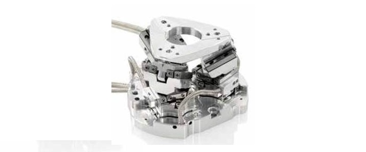
Figure 5. Miniaturized 6-axis parallel-kinematic SpaceFab positioning system.
The six degrees of freedom enable the secondary platform to move in three linear directions, lateral (X) and longitudinal (Y), vertically (Z), and the three angular directions (pitch, roll and yaw), by the legs. Thus, hexapods can perform manipulations that encompass total freedom of motion in a relatively compact space, with high stiffness and without moving/sweeping cables that can break and foul.
Vacuum Compatible Positioners
Vacuum applications are increasingly more important for many fields of research and industrial manufacturing. Requirements span from vacuum levels from 10-3 mbar to 10-9 mbar. While piezoceramic drive units can easily be modified for extreme vacuum, an increasing number of motorized positioning devices are also being incorporated successfully into vacuum applications where long travel and high precision motion are needed.
Positioning systems specifically developed for vacuum operation must meet a number of criteria. Because of limited space within vacuum chambers, the selection of suitable components is crucial for the vacuum compatibility of a positioning system. The body of the positioning device must be designed for placement in closed compartments, to avoid outgassing. Holes, as well as screws, need to be vented, and a reduction of the surface is desired. Air pockets, such as in under mountings, must be avoided as they considerably delay pump-down to target pressure or even make generating a stable vacuum impossible.
The article was written by Stefan Vorndran and Scott Jordan from Physik Instrumente L.P. Vorndran is Vice President of Marketing, while Jordan is Senior Director of NanoAutomation Technologies.
Filed Under: Encoders • linear, Encoders (rotary) + resolvers, Motion control • motor controls, Motors (direct-drive) + frameless motors, Motors • stepper


