 Electric motors are absolutely essential to automating innumerable applications around the world. In most cases, the driving of motors — the supplying of electric power to them — requires some engineered system that must also be compatible with the motor’s winding arrangement. Because these motor-powering systems are often found employing or accompanying the other electrical control and connectivity devices already covered in this Design Guide, we’ll now review their most common permutations. Additional information on motor drives having functions beyond motor starters can be found at this motioncontroltips.com article.
Only the simplest and smallest designs — usually with single-phase motors 5 hp or smaller or three-phase motors 15 hp or smaller — accept direct-on-line (also called across-the-line) connection to the electrical power source without risk of a motor overdraw and a line undervoltage condition. Three-phase motors driven this way can have windings connected in a simple wye (also called star) or delta configuration … and dual-voltage motors (convenient for how they can accept 230 V or 460 V input) have twin coil sets that can run in parallel or (for the higher voltage) in series.

This Siemens SIRIUS 3RV2011-1HA10 size S00 circuit breaker is a current-limiting breaker for load feeders to 3 kW at three-phase 400 Vac. A short-circuit protection of 104 A and an adjustable overload protection of 5.5 to 8 A reliably protects electric motors. Image courtesy Automation24 Inc.
Everywhere else, across-the-line motor starts present too many problems for the motor itself as well as systems attached to the motor — including detrimental electrical effects as well as excessive wear on mechanical power-transmission components. The design objectives of safety, productivity, and precision usually necessitate the use of more advanced motor-driving approaches.

Starting current is an important parameter in the proper sizing and pairing of motors and motor starters. Starting current from the motor starter must be sufficient to help the motor meet torque and acceleration requirements but mustn’t cause excessive voltage drop on the electrical supply line.
Terminology groundwork: The difference between contactors and motor starters
In a previous section of this Design Guide, we detailed how contactors and relays are distinct components — despite occasional industry usage of the terms that suggests otherwise. Contactors and motor starters are also distinct components. Here the terms are used interchangeably because their core is the same exact technology — a switch capable of handling high voltages.

This direct-on-line motor starter is a SIRIUS 3RM1001-1AA04 from Siemens with a control voltage of 24 Vdc and an adjustable pickup current overload release of 0.1 to 0.5 A. It imparts solid-state motor protection and is suitable for systems with small motors up to 0.12 kW An industry-standard 22.5 mm width consumes minimal space inside control cabinets. Image courtesy Automation24 Inc.
The difference is that motor starters have one extra system or systems not found in contactors — an overload relay of some type to cut voltage input should that relay sense a motor-overload or thermally compromising condition due prolonged running overcurrent. Those designated as self-protecting motor starters also include short-circuit protection. Here again, precise use of terminology is key: Rather than using short circuit to refer to any electrical malfunction, it’s only proper to use the term when discussing a sudden overcurrent arising from the flow of electrical power that has found some unintended path of travel. Short-circuit protection acts instantaneously to cut off the system from the power source.

This is an example of a power contactor. It is a Siemens SIRIUS 3RT2015-1BB41 for supplying power to three-phase motors and electrical heating systems up to 3 hp at 480 Vac. The power contactor uses a control voltage of 24 Vdc features a NO contact and screw-type cable receptacles.
In fact, there are numerous sizes and versions of this power contactor for load feeders with circuit breakers — and various SIRIUS switching devices for the safe and functional switching of electrical loads.
• 3RT2 contactors come in sizes S00 to S3. 3RT1 contactors come in sizes S6 to S12
• 3RT.0 power contactors and 3RT12 vacuum contactors are for switching motorized loads
• Four-pole 3RT23 contactors (and three-pole 3RT24 / 3RT14 contactors) switch resistive loads
• Four-pole 3RT25 contactors are for changing the polarity of hoisting gear motors
• 3RH2 contactor relays switch in the control circuit
• 3RT26 capacitor contactors switch capacitive loads (AC-6b)
• 3RT1 / 3RT2 / 3RH2 contactors have extended operating ranges … 3RT10 / 3RT20 / 3RH21 contactors are for rail applications …and 3RT20 / 3RH21 coupling relays are for system-compliant interaction with electronic controllers
• 3RT1…-.S.36 contactors have failsafe control inputs for safety-related applications
Reversing contactor assemblies are also available — as are contactors for starting three-phase motors with reduced starting-current peaks ( in to form of contactor assemblies for star-delta arrangements.
Another difference between contactors and motor starters is related to how the two components are rated and specified. Contactors are generally classified by their voltage capacity. In contrast, motor starters are typically rated by their current capacity and the horsepower of the motors for which they’re compatible … even while accommodating inrush current upon startup without nuisance tripping. That is usually done through a slight delay in relay tripping — as many motors (especially smaller motors) can reach full operating speed in just a few seconds.

Circuit diagrams of sample variations of contactors, full-voltage motor starters, and soft starters show their differences and similarities. Click to enlarge.
Motor starting at its most basic level is classified as manual or automatic. Manual starting includes hand-turned on-off switches that simply make or break the motor input circuit when activated by plant personnel. Some versions that qualify as true motor starters (as designated above) incorporate a thermal-overload relay to de-energize the motor if it becomes overheated. In contrast, automatically triggered motor starting is sometimes called magnetic starting for the electromechanical contactors that are core to this design.
As with any electromechanical relay technology, these have stationary electromagnetic coils that (upon a command from a pushbutton, limit switch, timer, float switch, or other relay) force together two circuits. These circuits include input power contacts and a mating carrier that (once closed together) allow current flow into the motor windings. One variation on this design is a combination starter, which includes the magnetic action as well as some way of disconnecting electrical power when needed … either with a fuse, breaker, or motor circuit switch.
Wye-delta motor starting (one type of reduced-inrush system) sends full-line voltage the motor’s wye windings during startup — though voltage across each motor winding is reduced by the inverse of the square root of three (57.7%) which is why this arrangement is sometimes (rather inexactly) called reduced-voltage starting. Then a circuit (usually with a contactor for each phase, overload relay, timer, and mechanical interlock) switches the motor input to supply it full-line voltage into its delta windings.
Part-winding motor starting — used in conjunction with the specialty dual-voltage motors mentioned above — applies across-the-line voltage to only one part (half or two thirds) of the motor windings (typically nine or twelve) upon start. Then once a set time has passed or set voltage is detected, a relay or timer springs into action and commands that the rest of the windings be added and supplied power as well. Acceleration may be irregular, but part-winding motor starting impedance has no effect on starting torque … and allows low-torque starts that are useful for pumps, fans, and blowers. Like wye-delta starting, part-winding starting is a type of reduced-inrush system and delivers a diminished full-line voltage upon motor startup — but doesn’t technically qualify as reduced-voltage starting.
Full-voltage reversible starting leverages how induction motors change rotation direction upon reversal of any two power leads. Reversing starter systems simply incorporate a pair of mirrored contactors complemented by interlocking subcomponents to allow run-forward and run-reverse conditions. Quicker rotational-direction reversals can be made with plugging, which is the temporary powering of both circuits.
More controllable: Reduced-voltage motor starters
Besides the family of full-voltage motor-starting options are reduced-voltage starters. Where machine axes require smooth non-jarring acceleration to full speed (to protect attached machine equipment or some attached load) reduced-voltage motor starters are essential. In fact, they’re also useful in settings regulated by local power utilities that limit voltage fluctuations and current surges on power supplies during motor starting.
Reduced-voltage motor starters include four common subtypes.
Primary resistor motor starters
Primary resistor motor starters are a cost-effective option that uses resistors and some number of contactors — with the latter dictating the number of starting voltage steps. These steps can be somewhat abrupt due to the circuit’s low inductance. Though the resistors can be bulky and introduce inefficiency, this starter type delivers reliable motor-starting torque.
Primary reactor motor starters
Primary reactor motor starters are most common on large high-voltage motors. They employ a reactor (inductor) action in a circuit like that of a primary resistor motor starter. Relatively long smooth accelerations are possible (even to a dozen seconds or more) though additional system inductance can degrads overall efficiency — and a poor power factor degrades torque-generating current components and motor flux.
Autotransformer motor starters
Primary reactor motor starters are relatively costly but useful where adjustable start torque is required. Autotransformer motor starters use a single-winding electrical transformer — with the latter being a passive electrical device for transferring electrical energy from one circuit to another. More specifically, autotransformer starters employ a trio of electrical contactors on an autotransformer having selectable taps. That imparts stepped voltage starting for long smooth acceleration upon startup — even to a few dozen seconds. Start voltage can be 50% to 80% of line voltage for high start torques in applications where that (and not efficiency) is a leading design objective.
Soft starters
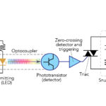
Soft starters employing solid-state semiconductor technology are capable of the most controllability out of all motor-starter options. They’re also the gentlest on motors’ internal subcomponents and attached power-transmission mechanisms. At their core, soft starters consist of various thyristor or SCR arrangements … so for example, some designs have a pair of thyristors on each of the three lines into the motor. Review this Design Guide’s section on solid-state relays for the basics of this technology. These switching devices work to control electrical power into the motor windings (as illustrated by the soft-starter diagram showing firing angles) while leveraging how motor voltage along with current and torque are low upon initial startup. Then they gradually raise voltage and torque according to a preset routine.
Motor soft-starter programming dictates the exact parameters of the increase to set voltage. Consider the operation of a representative SCR-based soft starter: Here a conducting (gated) SCR has a movable gate point … and adjusting back this speed value (called ramp time) causes an increase in voltage accumulation before the SCR switches on. Then once the motor windings reach full voltage, the SCR switches off.
One caveat: Excessive ramp time can make current exceed the motor’s safety limits or prompt a current-limit safety cutoff.
Besides the benefits already mentioned, soft starters impart motor protection (even during phase imbalances during electric-utility brownouts) as well as the ability to soft stop. The latter is helpful where motors drive designs such as conveyors that involve inertias capable of shifting or breaking during transport.
Of course, variable frequency drives (VFDs) are another option for soft-start functionality. They provide the same controlled starting and stopping functions of a soft starter, albeit in a different way — by varying motor-input voltage frequency rather than voltage magnitude. Other VFDs advantages over soft starters include the ability to control motor speed over the entire operating range. VFDs can also deliver power for holding torque (full torque at zero speed) which is key in motor-driven applications such as cranes and elevators.
However, for some designs VFDs are overly costly and complicated. Reduced-voltage motor starters tend to be more suitable than VFDs where there’s no gain in efficiency to be had from running the attached motor below its top speed rating.
You may also like:


Filed Under: Industrial automation, Drives (ac) + VFDs + starters, Relays, Motion Control Tips