 Download this article (and the rest in our connectivity series) at the Design Guide library.
Terminal blocks are one variety of connector component for joining sections of electronic circuits in industrial applications. They include electrically conductive assemblies having wire-securing receptacles — all encased in monolithic plastic housing. Some terminal blocks have contact pads or legs for connection to PCBs, but most are designed with their own housings for screwing onto machine frames, attaching to the sides of industrial electrical components, snapping into industrial rail and rack systems, or mounting to the inside walls of control-panel enclosures. Here we focus on the latter. Refer to the motioncontroltips.com article on DIN-rail geometries for more information on the DIN rails onto which many terminal blocks mount. Also refer to Design World sister site eeworldonline.com for more information on PCB terminal blocks — those that solder or otherwise mount to PCBs and connect thin-gage wires for low-voltage power and control applications between circuit-board components.
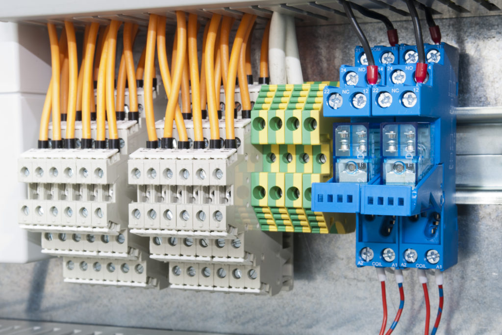
Mounted on this DIN rail are terminal blocks and (in the blue housings) relays based on electromechanical action.
Housed terminal blocks are most suitable for semi-permanent and permanent connections of signals and power … accommodating wire and cable sizes from the delicate 16 American Wire Gauge (awg) to what would be the logical equivalent of -7.5 awg — a beefy circular mil of 600 kcmil or MCM. Most all terminal-block designs provide reliable securing of wire as well as easy release of wire —to allow inspections, repairs, and replacement of wiring and attached components.
General-purpose terminal blocks (sometimes simply called electrical blocks or wire terminations) are broadly applicable in myriad applications as electrical-connection termination points. Other more specialized terminal blocks include:
• Terminal blocks for the transmission of I/O signals
• Terminal blocks for power distribution
• Terminal blocks for motor connections — including single-phase and three-phase motors for various industrial uses
• Terminal blocks to serve as ground blocks — designed specifically to make connection to ground)
• Terminal blocks to serve as fuse blocks — in which two wires make a connection to a fuse for circuit protection.
Unlike other connector options such as DIN cable connectors, pin headers, D-sub connectors, and industrial socket connectors, a single terminal block typically makes only one (single pole) wire connection to the electronic circuit at hand. That said, terminal blocks do come in multi-row banks for joining arrays of wires to circuits as needed.
Consider the special case of interface blocks. Also called terminal block interfaces, these are identifiable by their inclusion of two connector types … with one usually taking the form of a very long receptacle array to accept separate discrete wires. In fact, the job of an interface block is to connect an array of wires from a power component to pre-engineered cable (sporting a specialty connector) from a controller or other low-signal component. For example, one common interface might accept a 37-pin D-sub plug and connect it to a 38-position terminal block that holds the wires in their terminals with push-in contacts. Recall that the D-subminiature connector is named for its distinctive D-shaped metal plug shield … perhaps most familiar for its inclusion on older consumer-printer cable ends.
Terminal block interfaces abound for connecting various DIN headers as well as flat ribbon headers, IDC connections, and other industry-standard cable ends. Some safety-featured styles include dead-front wire receptacles that recess conducting elements into the plastic housing. Other styles have a stepped (tiered) design to save space and make it easier to access all wire receptacles even if one section of the block is already wired.

When selecting a terminal block, current ratings are paramount. Excessive current through a terminal block can induce overheating and failure. Voltage is usually less of an issue, but still a key terminal-block parameter: Excessive voltage (while rare) can induce dielectric breakdown and current leakage between adjacent blocks. A terminal block’s published creepage (between terminals) and clearance (through-air distance) values affect voltage ratings as well.
The receptacles on terminal blocks must be large enough to accommodate the designs’ cable gages. The wire type (single or multi-strand) in part dictates which terminal types are most suitable: Single-strand (single-core) wire is typically stiff enough to push aside the spring mechanism inside push-in connectors, whereas multi-strand wires are often used with screw terminals on terminal blocks.
More on the receptacles inside terminal blocks
Wire-contacting elements inside terminal blocks are often a copper alloy having the same thermal-expansion coefficient as the wire they accommodate. This avoids problems associated with differing expansion rates as well as those associated with electrolytic reactions when dissimilar metals touch. Where a terminal block will likely accept insertion of both single-conductor wire and stranded wire, some manufacturers make the wire-contacting elements of copper beryllium.
Terminal blocks with screw terminals employ screws to secure cable and wire in place. Typically found on blocks handling moderate voltages and currents, these require that the technician insert wires into open receptacles and then use a screwdriver to tighten a small plate down onto the wire to hold it fast. Larger terminal blocks may insert-mold metal receptacle linings to make the wire contact even more reliable. Subtypes of screw terminals are strap-clamp contacts (which use a wire-clamping screw and strap assembly) and tubular contacts. The latter use a rectangular metal tubing pierced by a screw at each end. This is called a tubular screw contact when the screw’s flat bottom holds inserted wire in place. It is called tubular clamp contact when a flat pressure plate on the screw end clamps the wire … which is a setup that’s useful for finely stranded wire.
Terminal blocks with barrier terminals also employ screws to hold conducting wires and cables fast. However, these have multiple termination points for multiple cables — as well as small barriers between individual terminals.
Terminal blocks with quick-connect contacts employ the mating of simple female tabs that accept insertion of flat male blades soldered to the end of wire needing connection. This friction-based mating is common for thin-wire applications and those that see regular service or reconfiguration.
Terminal blocks with push-in or push-fit contacts (sometimes called spring-loaded contacts) have open receptacles to accept manual insertion of wire and cable. Then a flat-spring-loaded mechanism embedded at the root of each receptacle bites into the cable and traps it via mechanical wedge action against the receptacle’s interior wall. These designs include pushers called release plungers (depressed with the use of a flathead screwdriver or more specialized poker tool) to temporarily hold back the spring-loaded mechanism if the wires loaded into the terminal block need to be removed for some reason. In some cases, these pushers are brightly colored — for easy identification and to make it easier for technicians to see where to apply screwdriver pressure.
Push-in contacts are increasingly common on terminal blocks that mount on DIN rails because they avoid issues associated with the overtightening of screws and often make the wiring of terminal blocks go faster.
Closely related to push-in contacts are tension-clamp contacts. A spring-loaded mechanism holds the wires in their receptacles … but the difference is that the spring takes an a shape inside the receptacle. That means it necessitates the use of release plungers (depressed with the use of a flathead screwdriver) for both removal and insertion of wire. Terminal blocks having receptacles made with this design are useful when reliability is a top design objective.
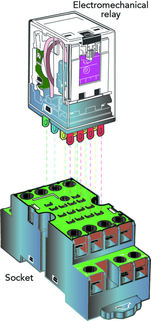
Sockets accommodate relays having a certain number of connector blades. These assemblies allow quick replacement of the relay in case of failure.
Pluggable terminal blocks have wire and cable input receptacles as expected — as well as a male plug output to insert into a mating socket. Such terminal blocks are indispensable for hot-swapping connections during inspection and service.
Besides selling components with these variants, terminal-block manufacturers allow for almost boundless customization. Just a few options include:
• Clear-plastic housing options and label sets (especially for terminal blocks that mount to DIN rail) to allow inspection, labeling, and organizing wire connections
• Switch or disconnect formats (as in knife-disconnect terminal blocks) with a plastic-molded throw that lets operators move a blade connector (embedded inside the block) into or out of a circuit — for a quick way to disconnect the circuit
• Lights and complementary circuits for visual annunciation of connection status
• Jumper straps to link adjoining contacts as well as fanning strips to allow the concurrent connection of wire arrays
• Sockets on terminal blocks for fuses and disconnect elements (especially for the accommodation of ferrule fuses of various ampacity ratings) for surge suppression and voltage regulation
• Sockets for the insertion of PCBs (to impart advanced functions)
You may also like:
Filed Under: Factory automation, Industrial automation, Relays, PLCs + PACs

