 Solid-state relays (SSRs) serve the same functions as electromechanical relays but are non-moving noncontact devices that can switch voltages to several hundred Vac for hundreds of thousands of cycles and beyond … which makes them useful for switching heating elements, motors, and transformers needing frequent and high-speed switching. ⚙️ Download this article (and the rest in this connectivity series) at the Design Guide library.
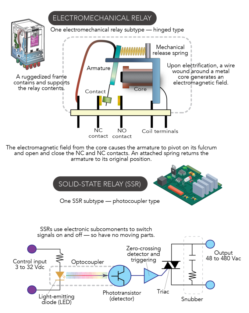
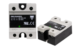
Electromechanical relays and solid-state relays use different technologies to perform essentially the same function. The fast switching of SSRs makes them suitable for use on myriad high-power loads.
In contrast with electromechanical relays, the subcomponents in an SSRs are entirely electronic:
1. An SSR’s input circuit (like the coil of an electromechanical relay) connects to a system control. As voltage entering the SSR changes — 3 to 32 Vdc is common — it prompts the input circuit to act. In one common variation, the circuit activates upon application of any in-range voltage exceeding the relay’s pickup voltage value … and deactivates upon reduction of input to below the relay’s dropout voltage value.
2. An SSR’s coupling communicates energization and de-energization commands to the relay output — acting as the go-between between the input and output circuits. Note that this portion of an SSR is specially engineered to ensure the input circuit interfaces with the output circuit in a galvanically isolated way … so that high-power (output) load current is segregated by the relay’s coupling section. That reliably prevents load current from flowing to the relay input — even during system failure.
Various technologies are used for the coupling portion of an SSR:
The most common type, photocoupler SSRs, uses an LED or infrared light source on the input circuit to communicate with a photosensitive semiconductor on the output switch side. In contrast, transformer-coupled SSRs use a dc-ac converter to generate output that magnetically couples to the output via a low-power transformer.
3. Next an SSR’s trigger or drive circuit connects one of several designs taking the form of a:
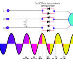
• Silicon-controlled rectifier (SCR) for high-speed switching of (usually) short-duration “on” periods
• Back-to-back thyristor called a triac — short for triode for alternating current
• Metal-oxide semiconductor field-effect transistor (MOSFET) or Darlington transistor (for dc)
• Insulated-gate bipolar transistor (IGBT) for dc
Here, zero-switching operation — the most common for SSRs — as well as peak switching, dc switching, and instant-on switching are all options to tailor the relay action to the type of load the system drives. For example, analog switching uses a synchronizing circuit to make output voltage track input voltage — and allow a wide variety of possible output voltages within the SSR’s allowable range. These excel in soft-start designs to drive electric motors.
4. Beyond that, an SSR’s output (power) circuit connects to the load being controlled. Past the switch it may also include a snubber circuit (in some cases, a reverse-connected diode) or a zero-crossing detector to reduce spikes and transients and electromagnetic interference (EMI) during switching. That’s an issue because SSRs switch load current through attached inductive loads — and (according to Faraday’s law) current interruption induces voltage rise. Any such rise across the SSR exceeding the maximum ratings may cause damage.
Where SSRs excel
SSRs are compatible with a variety of control systems and are immune to magnetic noise; their solid-state nature means they mount in various orientations … and SSRs are impervious to heavy vibration. It’s true SSRs are more expensive than certain alternatives but the most sophisticated can deliver exceptionally long life.
Consider a few electric-motor applications of SSRs:
• On the motors of large conveyor belts or assembly lines with the potential to jam
• On industrial motor blowers for commercial ovens at risk of being overworked should a door be left ajar
• On motors subject to overcurrent conditions or incorrect starting currents
• On neglected motors and those attached to wearing mechanical components exhibiting excessive friction
• On general-purpose electric motors subject to high-temperature environments
Such motor-driven machinery may incorporate protective relays (electromechanical relays and SSRs) on their power supplies to both sense any such overheating and turn off the motor to prevent damage. The use of durable SSRs in such applications is widespread, because they have no moving parts to degrade life of accuracy … and in fact often outlast the equipment on which they are installed.
Managing the heat from SSRs
The information presented here about thermostats on SSRs originally appeared at Design World’s sister site eeworldonline.com.
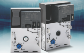
Semiconductor-based switches as found in SSRs generate non-negligible heat — and left unaddressed, this can present a risk of mechanical fatigue due to thermal cycling. Two solutions here are heat sinks and thermostats. Thermostat can be added to SSRs by design engineers (who assume the design of the thermal protection) or pre-integrated by the SSR manufacturer.
In some SSRs with pre-integrated thermostats, the SSR cuts off input circuit power when the temperature of the SSR itself goes beyond the specified maximum as determined by the application requirements. After a brief cooldown, power is automatically turned on again. Here, the SSR’s thermostat senses the internal temperature of a mechanical interface with a metal plate at the mount for the internal power-switching device. If the heat exceeds the normal range, it sends a signal to the SSR to turn off the power.
This built-in thermal protection prevents overheating conditions by providing a trip before equipment damage can occur, thereby saving time and money.
For machine designers wanting to leverage this technology and save themselves the trouble of doing it themselves, it’s first necessary to select the appropriate SSR for the load needing control. One key consideration is the application’s ambient operating temperature, which factors into the best derating for ampacity. In other words, engineers must identify the maximum power rating, current rating, or voltage rating for which the SSR is rated — and then use less than those maximum ratings.
Other design considerations are the heatsink used and anticipated power dissipation.
SSRs benefiting from most from such built-in thermal protection include those on industrial ovens, commercial refrigeration systems, sterilization equipment, welding equipment, and conveyors in packaging, construction, and material handling.
MEMS mechanical switches compete with SSRs
When microelectromechanical systems (MEMS) were first introduced in the 1980s, they were touted for their ability to subminiaturize electromechanical contacts. Built on silicon substrates using the same etching processes to make conventional ICs, MEMS structures work in inkjet printing heads, accelerometers, pressure sensors, and elsewhere. But they’ve yet to displace conventional mechanical switches … in part because MEMS switches’ tiny contacts can’t handle much current. Plus MEMS switches can exhibit arcing and heating that cuts switch life short.
But now, MEMS devices employing Digital-Micro-Switch (DMS) smart power relay technology could soon spur more use of MEMS-based power relays. These combine the benefits of solid-state and electromechanical relays. Read the full story at Design World sister site powerelectronictips.com. The DMS parallels a MOSFET with a MEMS switch to get zero-voltage switching. This reduces the switching energy across the contacts — which in turn boosts reliability under high voltage and current. The switch design also uses metal processing to boost the reliability of the cantilever beam holding one side of the contact — as well as the contact material itself. It makes for devices capable of three billion cycles and beyond. In fact, the power relay retains the galvanic isolation properties of traditional relays … and it can integrate into traditional semiconductor packages to provide other intelligent features.
You may also like:


Filed Under: Factory automation, Industrial automation, Relays