By Greg Cober, Boston Gear Product Training Manager, Boston Gear
It may be conventional wisdom that using a helical gearbox design will lead to more system efficiency than using a worm gear design. However, advances in worm gearbox design as well as improvements in lubrication are closing the efficiency gap to the point where the cost-effectiveness of worm gearboxes is more than competitive with helical designs.
Right-angle worm gearboxes that previously had efficiencies of 82 or 83% are now showing ratings in the upper 80% ranges, while units that were in the upper 80% range now 93 to 94% efficient. Some manufacturers have made greater strides in these efficiency improvements than others.
Generally speaking, right-angle worm gear reducers begin to see drops in efficiency as they cross into higher ratios. Larger center distance worm gearboxes are generally more efficient than smaller center distances. For example, a standard unit with a 2.6-in. center distance sees efficiency decrease slowly as ratio increases.
Similarly, as center distance grows, efficiency improves, as seen here where the rise in efficiency for seven center distances is at a 10:1 ratio.

Right-angle worm gear reducers tend to lose efficiency as they cross into higher ratios. Larger center distance worm gearboxes are generally more efficient than smaller center distances. For a standard unit with a 2.6-in. center distance, for example, efficiency decreases slowly as ratio increases.
The challenge is what is the trade-off between purchase price and cost savings through efficiency? Is it more economical to pay extra for higher efficiency or is the cost of that efficiency too high to recapture through lower operating costs?
When comparing the energy savings for a helical gearbox compared to a worm gearbox in the same application, there are many situations where the dollars saved are minimal. As a general statement, the multiple stages required within a helical gearbox add complexity and cost. Helical gearboxes are generally more expensive than worm gearboxes for the same HP and gear ratios. When the energy dollars saved are compared to gearbox purchase costs, there are strong reasons to consider right-angle worm gearboxes in many lower HP applications.
To compare the savings in some common lower HP applications, we have calculated the dollar cost to operate a motor at full-load current for an 8-hour shift using a standard ac motor. Motor costs are calculated using a US Department of Energy website which identifies a national average industrial power rate of 6.3 cents per kilowatt-hour as of March 2012.
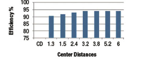
As center distance grows, efficiency improves, as seen here where the rise in efficiency for seven center distances is at a 10:1 ratio.
Based upon market prices and catalog stated efficiencies, the payback time for low HP applications can be long. For example, in a simple application for a 1 HP unit with a 10:1 reduction, the cost of a worm gearbox is $840 less than the equivalent helical unit. The efficiency of the worm gearbox would be 92% compared to a 97% for a helical gearbox.
In an application for a 1 HP unit with a 10:1 reduction, you can conservatively expect to pay a $300 or more premium when using a helical right angle gearbox instead of a worm right angle gearbox. Even the most efficient helical reducer will not exceed 97% (more typically it is in the low to mid 90% range). So, you can use an efficiency of 97% as the best scenario for the helical right angle reducer, as compared with 92% for worm reducers that are manufactured using current technology. That converts to less than a penny per hour of operation. At that rate it would take more than 200,000 hours of operation to recover the difference in costs between the two.
As noted, the higher the ratio, the lower the efficiency of the gearbox. For the same 1 HP application, a 30:1 ratio would see a worm gearbox efficiency drop to 81%. Even in this instance, the purchase price differential between a helical and a worm gearbox is high enough that the time to make up the cost difference would be 48,000 hours.

This chart shows the potential dollar cost to operate a motor at full-load current for an 8-hour shift using a standard ac motor. Motor costs are calculated using a US Department of Energy website which identifies a national average industrial power rate of 6.3 cents per kilowatt-hour as of March 2012.
The crossover point, where it becomes more efficient to use helical rather than worm gearboxes, is at the 10 HP range with ratios above 20:1. With low ratios, the worm gearbox still has a lower purchase cost compared to the helical and still has an efficiency of 94%. But, as ratios rise, the relative efficiency decreases and, in higher ratios, the purchase cost and efficiency ratings both show that the helical gearboxes may be a more cost-efficient design at both purchase and cost of use.
The purpose of these examples is not to imply that worm gearboxes are more suitable than helical gearboxes in all applications. You will find that in applications requiring higher torque (for example 10 HP at a 30:1 ratio), a helical reducer generally provides a better solution. In this example, the difference in efficiency plays a larger role in the TCO calculation and allows for the capability to downsize. The overall takeaway is that it is very important to compare published efficiency ratings of both helical and worm gearboxes for the applicable HP and ratio during the specification process.
Boston Gear
www.bostongear.com
Filed Under: Gears • gearheads • speed reducers

For example, If we consider a conveyor, suppose for a stone crusher where required ratio is 30/1 and motor kw 7.5 hp. So, for a stone crusher we have to consider the heavy load, the steep angle for a conveyor also being a factor and 22 hours running time. which would be better to choose.. ?
I am running 1:15 ratio worm gear box with 1 H.P.Motor Drive having rated RPM: 1400 / 4P – UP/DOWN Conveyor Appplication.Can I run the same gear box with 2800 RPM / 2P Motor.Does this higher speed RPM motor will damage the gear box.You are requested to answer to this SOS.
An important distinction not mentioned here is that helical gearboxes can be back-driven while worm gearboxes cannot. I was designing a gearbox reduction for a hybrid motor/pedal vehicle and when the motor is off but passengers are still pedaling a worm gear box would lock up the drivetrain.